ATA Hard Disk Installation Troubleshooting Tips

ATA Hard Drive If your system hangs or locks up during the boot process after installing your new Maxtor Hard drive, either before or after setting the system BIOS, this indicates a jumper conflict with another device on the cable or a BIOS capacity barrier.

If this happens, please perform the following:

  1. Turn the system off.
  2. If the drive is on the cable with another device disconnect both devices from the cable. You will need to test the Maxtor drive as a “stand-alone unit” on the cable. Install a jumper on the cylinder limit / alternate capacity jumper, reconnect the ATA and power cables and restart the system.
  3. If the BIOS is set to AUTO-DETECT and the drive is now detecting without hanging the system, proceed with partitioning and formatting the drive with the MaxBlast software*. The device you removed from the cable in step 2 can now be reinstalled on the ATA cable. If the system continues to hang after reinstalling the second device, you will need to verify its jumper settings or place it as a stand-alone device on the secondary ATA port.
  4. If the system is still hanging after installation of the cylinder limit / alternate capacity jumper, you will need to try the user-definable option in the BIOS setup utility. Power the system off and disconnect the 40-pin ribbon cable from the drive (this will prevent the system from hanging while performing the next step).
  5. Restart the system and enter the BIOS setup utility, set the BIOS parameters to a User Definable Type with 1024 cylinders, 16 heads, 63 sectors, and set the LBA mode to normal or standard. Ignore the Write Pre Comp (WpCom) and Landing Zone (LZ) settings (they can be set to zero). Save settings, exit setup, and power system off.
  6. Reconnect the cables and power the system on. If the system no longer hangs, proceed with partitioning and formatting the drive with the MaxBlast software*.
  7. If you tried all the above steps and are still experiencing problems, the only options left are contacting your motherboard manufacturer for a BIOS Upgrade, or purchase an ATA controller card.
Read More

What is Logical Block Addressing (LBA)?

Logical Block Addressing (LBA) is a mathematical scheme for addressing sectors, beginning at cylinder 0, head 0 and sector 1, which is equal to LBA 1. This scheme linearly maps the drive until the final physical sector is reached. LBA is efficient because it reduces some system overhead by not having to convert the operating system’s LBA to the BIOS CHS and then back to drive LBA.

Read More

An Old IDE Drive May Not Work With A New IDE Drive?

Why is it that an Old IDE drive may not work with a New IDE drive?

The reason is the fact that many hard drive manufacturers were already making and selling drives before the IDE standard was clearly defined. Older IDE drives have problems functioning in dual-drive configurations. This scenario is more prevalent when the hard disk drives are from different manufacturers; in some cases, two drives may not function together at all. However, in rare circumstances even new drives will not work together.
Solution:

  • Separate the drives and have them on their own cable. Designate one drive as the Primary Master and the other as the Secondary Master.
  • Try not to jumper the drives as Cable Select. Have the drives jumpered as a “Master” drive.
Read More

MS-DOS Compatibility Mode Issues

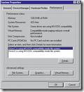
MS-DOS Compatibility Mode Issues The Performance tab in System Properties shows that one or more of the hard disks in your computer is using “MS-DOS Compatibility mode“. MS-DOS compatibility mode may be in use for either the file system or for virtual memory. You may also receive the following message: “Compatibility Mode Paging reduces overall system performance”.

This is not an operating system issue and it is not a hard disk drive error. MS-DOS Compatibility mode may be in use for any of the following reasons:

  • An ‘unsafe’ device driver, memory-resident program, or virus hooked the system interrupt (INT21h or INT13h) chain before Windows loaded.
  • The hard disk controller in your computer was not detected by Windows.
  • The hard disk controller was removed from the current configuration in Device Manager.
  • There is a resource conflict between the hard disk controller and another hardware device. The Windows protected-mode driver is missing or damaged.
  • The Windows 32-bit protected-mode disk drivers detected an unsupportable configuration or incompatible hardware.

Related Links:

  • Troubleshooting MS-DOS Compatibility Mode On Hard Disks
  • Large IDE Hard Disk May Run In Compatibility Mode
  • MS-DOS Compatibility Mode When Booting from Removable Drives
  • MS-DOS Compatibility Mode Problems with PCI-IDE Controllers
  • Windows Support for Large IDE Hard Disks
  • Packard Bell Legend Hard Disk Using MS-DOS Compatibility Mode
Read More

IDE/EIDE Interface Part I

IDE/EIDE Interface This is a general description of the most frequently asked questions about the IDE/EIDE Interface. This information is meant only to address basic troubleshooting of IDE/EIDE compatibility issues, and is not meant to be an in-depth discussion of all possible error issues. Our purpose is to aid you in solving basic IDE/EIDE difficulties that may arise.

Issues Covered:

  • IDE/EIDE Definitions
  • Compatibility Issues

1. What is IDE/ATA?
Integrated Drive Electronics (IDE) is a generic term applied to any drive with an integrated (built-in) disk controller. The first drives with integrated controller were Hardcards. In the IDE architecture, the disk controller is integrated into the drive. This combination drive/controller assembly usually plugs into an interface on the motherboard or an interface card plugged into an empty bus slot. The ATA Specification is simply a set of rules or guidelines that an IDE drive should conform to.

2. What does the IDE interface actually do?
The primary job of the IDE interface is to transmit/receive data to and from the drive.

3. Why place the Controller on the drive itself?
Placing the controller on the drive gives IDE drives built-in reliability because data encoding, from digital to analog is performed directly on the drive in a tight, noise-free environment. The timing-sensitive analog information does not have to travel along ribbon cables that may pick up noise and insert propagation delays into the signals. The integrated configuration allows for increases in the clock rate of the encoder, as well as the storage density of drive.

4. What is Enhanced-IDE (EIDE) and Fast-ATA?

Enhanced IDE (EIDE) was a marketing program first initiated by Western Digital. EIDE has two sides:

  • Software – the Enhanced BIOS Specification that surpasses the 504 MB hard drive capacity limitation
  • Hardware – hard drives that conform to the ATA-2 and ATA-PI Standards

Fast-ATA, EIDE’s counterpart, was a separate marketing program that was introduced by Seagate and Quantum. This program leaned conservatively toward the ATA-2 specification.

5. What are the main features of EIDE

These are the main features:

  • Faster transfer modes- PIO modes 3-4, DMA mode 2 and UDMA.
  • Multiple Read/Write commands
  • LBA mode, translation for drives larger than 504 MB
  • Four devices on the ATA controller (secondary port)
  • CD ROM and Tape Drive support

6. Is ATA-5, 6 or 7 compatible with older IDE drives?

Older IDE peripherals will work with newer enhanced drives. However you will not be able to fully utilize the enhanced features of your ATA-5, 6 or 7 peripherals.

7. Is ATA-5, 6 or 7 compatible with older IDE controller cards?

EIDE drives are backward compatible with non-EIDE (standard) controller cards. However, an EIDE card will only perform at the capabilities of the controller; hence the EIDE drive will perform like a standard IDE drive.

8. What is ATA-PI

AT Attachment Packet Interface (ATA-PI) is a standard that implements SCSI like devices on the ATA bus. Devices like CD-ROM’s, tape drives and other removable media. The advantages of ATAPI are:

  • It is inexpensive
  • It is easy to implement in current systems.

ATAPI’s disadvantage is that it requires the use of software drivers for operability.

9. What is Cable Select (CSEL)?

Cable Select (CSEL) is an optional feature per the ANSI ATA specification. It is an alternative method of identifying the difference between device 0 and device 1 on an IDE interface cable. Hard drives configured in a multiple drive system are identified by CSEL’s value:

  • If CSEL is grounded, then the drive address is 0.
  • If CSEL is open, then the drive address is 1.

Additionally, CSEL requires a specialized (and more expensive) 40-pin 80-wire IDE interface cable, unlike the standard EIDE interface cable that is far more commonly used. We do not recommend using the CABLE SELECT feature unless your specific computer system documentation requires its use.

10. How does my computer know which drive is the Master and which is the Slave?

When only one drive is installed, the single drives controller responds to all commands from the system. When two drives (which means two drive controllers) are installed, both controllers receive all commands from the system. Each drives controller must then be configured to respond only to commands issued to it. In this situation, one controller must be designated as master and the other as slave. When the system sends a command to a specific drive, the other drive’s controller must remain silent. A special bit (the DRV bit) is used in the Drive/Head Register to distinguish between the controllers.

Read More

IDE/EIDE Interface Part II

IDE/EIDE Interface This is a general description of the most frequently asked questions about the IDE/EIDE Interface. This information is meant only to address basic troubleshooting of IDE/EIDE compatibility issues, and is not meant to be an in-depth discussion of all possible error issues. Our purpose is to aid you in solving basic IDE/EIDE difficulties that may arise.

Issues Covered:

  • IDE/EIDE Definitions
  • Compatibility Issues

11.Why is the 20th hole plugged on the Ribbon Connector?

It is a means of preventing the cable from being installed (plugged in) upside down. Users that inadvertently plug a cable in backwards can cause damage to both the hard drive and the motherboards interface. If your system does not have the corresponding missing pin, you may remove this plug by “teasing it out” with a straight pin.

12. Does the IDE interface cable influence data integrity, signal noise issues and drive recognition?

The answer is Yes! The ATA standard specifies that an IDE Interface cable should be no longer than 18 inches. The standard cable used today conforms to the ATA specifications. However, 40 pin interface cables do not always filter out noise when used with the Ultra DMA 33, 66, 100 and even 133 hard drives of today. Another option for reduction of cable noise would be to use an 40-pin 80-wire interface cable. These cables provide better grounding to maximize signal integrity.

13. Will adding an EIDE Interface increase disk performance?

Although most, if not all computers manufactured today have the fastest interface available, the answer really depends on the hard disk drive. Unless you’re working with legacy equipment, a new interface may not give you a performance increase. As an example, upgrading an ISA controller to a PCI controller would be the biggest improvement a user could make.

14. Why is the hard disk drive NOT as fast as advertised?

Advertised transfer rates are based on the fastest speed at which the drive can send data across the ribbon cable from the drive buffer, with the transfer stopping temporarily every time the buffer re-fills. This process continues until a command is complete. Data transfer rates will differ between system configurations, as a drive is not the single component that decides transfer rates. The one thing that designers have control of is the speed at which data transmits across the data ribbon cable from the drive’s buffer, but not how your other components interact with the drive.

15. Why is it that an old IDE drive may not work with a New IDE drive?

The reason is the fact that many hard drive manufacturers were already making and selling drives before the IDE standard was clearly defined. While this is now, for the most part, relegated to very old IDE drives that have problems functioning in dual-drive configurations. This scenario was more prevalent when the hard disk drives are from different manufacturers, however, in some cases, two drives may not function together at all. Even today though, in rare circumstances even new drives will not work together.

16. Why is my new IDE drive not recognized as a slave or a master?

Configuring IDE drives can be simple, as is the case with most single-drive installations, or troublesome, especially when mixing drives from different manufacturers on a single cable. Most IDE drives must be configured in one of the following ways:

  1. Single-drive (master)
  2. Master in a dual-drive system
  3. Slave in a dual-drive system

Because each IDE drive has its own controller, one drive must be jumped as a master and the other as the slave. There are no functional differences between the two, except that the drive that’s specified as the slave will assert the DASP (Drive Active/Slave Present) signal after a system reset to inform the master that a slave drive is present in the system. Daisy-chained hard disk drives that do not have their jumpers set correctly will not function. You should contact the disk drive manufacturer if you are unsure of proper jumper settings.

17. Two hard disk drives will not function even after verifying jumper settings. What could be wrong?

There may be a compatibility problem between the two drives. Use the following steps to verify the function of each drive:

  1. Test each drive by itself, making sure that each drive has been jumpered correctly. If both drives work by themselves, you may conclude that there is a compatibility problem.
  2. Try “swapping” (switching) the drive’s position, what was the master will be changed to a slave and the slave will become the master.
  3. Most motherboards have two IDE bus connectors. Place one drive on each IDE bus and test the system.

18. Why does an IDE CD-ROM and Tape Backup not work when attached to the Interface?

On  occasion, attaching an IDE CD-ROM or tape backup drive to a bus that supports an IDE drive, can slow down and even compromise the drive’s data integrity. Although this is extremely rare today, make sure that your systems motherboard has an Enhanced IDE interface that is ATAPI compliant. If it is not, you can purchase and add-in card that has this interface, and they usually come with a secondary IDE interface built on the same card.

19. Even after switching roles, my hard drives still will not work. What else can I do?

First, see questions 16 and 17 above. We recommend that you separate the hard drives and connect them to the different interface ports (IDE buses) of the system. If the system does NOT have a Secondary IDE interface, we recommend that you install an EIDE interface card. By doing so, each of your drives would be able to communicate individually with the system. Enhanced EIDE cards also can add BIOS LBA support and enhanced performance for the drives.

20. Why are 80-wire, 40-pin ribbon cables required for certain hard drive configurations?

40-conductor cables support only up to 33MB/sec transfers (and should only be used for up to 16MB/sec or less in our opinion), while 80-conductor cables support up to 100MB/sec. Thus you can always replace a 40-conductor cable with an 80-conductor cable, but not the other way around without seriously hurting transfer speeds, and quite possibly damaging one or more of your systems components.
Read More

Hard Drive Crash

Hard Drive Crash Sometimes a hard drive may experience failure or sudden crash without any warning, but many times there are warning signs that will let you know when to take action. Changes in performance, intermittent failures, or unexpected blue screens are major signs that the hard drive may be dying out permanently. The most obvious warning sign with a hard drive is unusual clicking, grinding, or scraping noises.

In practice, the term hard drive crash often refers to both mechanical or electrical failue and logical failure. The case of mechanical / electrical hard drive crash is the worst, it requires professional help of data recovery service, recovery programs won’t help.

Hard Drive Crash Signs

If your PC is experiencing any of the following signs of impeding doom then you must run (not walk) and grab CDs to burn backups of all your essential data.

Sign 1 – You hear high-pitched whining, loud clicking or grinding noises coming from the drive
A normally operating drive will make a smooth “whirling” sound as is spins up or down. But if a drive has a grinding or clicking sounds (the Read/Write heads scraping too close to the magnetic platters), then your drive is sick and is on the way out.

Sign 2 – You see the infamous “Blue Screen of Death“, repeatedly
BSODs (Blue Screens of Death) are actually called “Stop” errors and they only appear when your Windows system is experiencing severe software or hardware issues. Often BSODs can cured with a careful “Repair Install” of the Windows operating system or by removal of a bad device driver. But if these software fast fixes don’t seem stick, then your hard drive is usually on its last legs

Sign 3 – Your computer keeps re-booting on its own
I admit, I have only seen this problem a few times in my 18+ year career and in all instances it was due to hardware issues. Once it was a dust covered motherboard, and another time an overheating processor. But all the other times it was due to bad drives.

Sign 4 – Your system keeps having frequent freezes or hang ups
You are working along just fine, and then suddenly everything comes to a halt. The program freezes up on you. Your mouse and keyboard seem to stop responding. The only solution is to reboot.

Sign 5 – Error message: hard drive is not formatted
This a fun message that you will get when you start up your machine. You maybe able to restart and get it to boot into Windows a few more times but this error is “fur-sure” sign that you drive is very close to death. And by the way don’t try to format the drive! You will lose all your data.

Sign 6 – Error message: boot drive or device not found or drive cannot be accessed
This is another favorite of mine. You can check the CD/DVD trays or the floppy drive to make sure no stray disks are stuck inside. You can also check the BIOS to make sure the system is booting from the hard drive first. If all these tests are no-good, then the drive is a goner.

Sign 7 – Errors: Operating system not found or Missing Operating System
This is a bad one. Even the Microsoft technical support knowledgebase has only got a few causes for this error message. Basically your PC can no longer detect the hard drive or the drive is too severely damaged to read (DOA).

What to do if your drive has any of these signs?

1) First, listen up, if possible, BACKUP YOUR FILES NOW!
2) Create a boot disk and run Windows Scandisk and set it to automatically fix errors. If it finds more than a few bad sectors then see the point above
3) If possible download and use a hard drive diagnostic program. All the major hard drive manufacturers have free utilities on their websites.

WARNING:

You should never open the cover of a failed hard disk drive in attempt to repair, salvage or recover data. Today’s hard disk drives tolerances are very tight and the materials used inside are so technologically advanced that even the smallest speck of dust, contaminants or even gaseous can disrupt the delicate balance of the drives ecosystem. Any such disruption not only destroys the drive but all the data contained on it.

Read More

Sustained Data Transfer Rates For SCSI Hard Drive

Data Transfer Rate Many factors contribute to disk drive performance. One useful measure is data throughput rate or sustained transfer rate. In general, higher data transfer rates from the disk to the computer lead to improved system performance. Data transfer rates are often quoted within the “Specifications” section of the product manuals. Yet it is important to realize that controller overhead, cable quality and termination issues (on older SCSI products) are major factors that affect sustained data transfer rates.

The following specifications are from an older SCSI hard drive. These numbers are used for example, but the same calculations apply to ATA drives. Notice that the internal data transfer rate is listed as sustained, while the external data transfer rate is listed as burst.

INTERNAL DATA TRANSFER RATE (Megabits/sec.)____194 to 340 (sustained)

EXTERNAL DATA TRANSFER RATE – Buffer to SCSI controller (Megabytes/Sec)___Ultra160/m 160 MB/Sec. (burst)

As there are 8 bits to a byte, and 8 Megabits (Mb) to a Megabyte (MB), we divide 194 Mb’s/sec. by 8 to get 24.25 Megabytes/sec. The drive should sustain a transfer rate of 24.25 MB/sec. from the drive platters to the read/write heads, even under the worst possible conditions. The lower number of the range measures data transfer from the inner diameter of the drive platters, where there are the least amount of sectors per track. The higher number of the range measures data transfer from the outer diameter of the drive platters, where the number of sectors is higher per track. Using the higher number of the range (340), the result is 42.5 MB/Sec.

We then have a data rate in Megabytes, of 24.25 to 42.5 MB/sec. Since this is an ‘internal’ data transfer rate, consider it as the raw data rate. Some of this internal rate is lost when translating to the user data rate, because this raw data includes coding overhead that adds length to the user’s data. Add a 25% allowance (more for some drives) for system overhead. In the case of this older SCSI drive, the overhead is approximately 30%. The sustained (user) data rates are actually listed at 17 to 29 MB/Sec. For drives where only the internal data rate is listed, the formula ([Internal rate in Mb/8] x .75 = Approx. data rate in MB ) is used to develop an approximate user data rate.

Most of the time you won’t be getting the lowest sustained transfer performance or the highest, so we should find an average. Using the average of the sustained transfer rates ([17+29]/2=23), you receive an expected average sustained data transfer rate of 23 Mbytes/sec.

It’s very important to realize how these numbers are presented. The internal data rate shown here is expressed in Megabits/sec, the user data rate is written in Megabytes/sec. Certainly, we can tell you, assuming your SCSI (or ATA) subsystem is configured correctly, what your expected sustained transfer rates should be. In this case, a sustained transfer rate of 17 MBytes/sec. to 29MBytes/sec. is acceptable. Your transfer rates may be higher–or lower.

If your sustained user data rates are lower than expected, this indicates a bottleneck in the system. A failing device, improper configuration, and termination issues are leading causes for poor performance. Be aware that transfer rates can be reduced by several issues–poor quality cables, improper cable routing (causes signal reflection), SCSI Single Ended devices on an LVD SCSI bus, host limitations and more.

While you might expect to see 320 MB/sec. transfer from your SCSI Ultra 320 devices, or 300 MB/sec. from a SATA drive, know that these specifications are the burst rate–what the drive’s cache memory buffer can process under the absolute perfect combination of drive, cable, and hard drive controller conditions. Even ambient temperature affects transfer rates. This is not the sustained transfer rate of the drive. It’s what the input/output subsystem is capable of handling. For hard drives, sustained transfer rates are an important benchmark. Only when combining several high-speed drives together (in a performance RAID array), does one approach ‘bus saturation’ speeds.

Read More

Data Recovery Training: Training Courses And Price

Data Recovery Training Courses And PriceWith data recovery training, You will learn the fundamentals of hardware data recovery which will enable you to properly diagnose dead drives and bring them back to life. You will also learn logical recovery for Windows, Mac OS X, Linux, RAID arrays, Exchange server and even solid state flash NAND drives!

This class does not rely on you purchasing an expensive tool (such as the PC-3000) to perform data recovery.

Total Hands-On Lab Environment in Data Recovery Training:
This Data Recovery Training neatly meshes the skills required in order to recover lost data. Some of the attention-grabbing lectures and hands-on lab exercises you will do during the class:

  • Logical Recovery of disabled hard drives
  • Using file format recognition tools
  • Logical recovery via avoiding BIOS interrupts
  • Motions that unlock the actuator of a drive
  • Diagnosing the physical recovery of drives
  • Comparing pre-recorded sound samples to live drives
  • Logic board replacements
  • Single and Multi-Platter Swaps
  • Head Assembly replacement
  • P-List and G-List recovery
  • Addressing SMART values
  • Dealing with damaged sectors
  • Reverse scanning
  • Capturing SID protected folders
  • Resolving kernel or driver issues with a Linux bootable disk
  • Head Stack replacement
  • Working with the Service Area (SA) of a drive
  • Reviewing data structures with a Hex Editor
  • Diagnosing “clicking noises”
  • Mac OS X Data Recovery
  • Linux Data Recovery
  • RAID 0 Recovery & RAID 5 Recovery
  • Vista and Recovery of Shadow Copies
  • Clearing passwords on a password protected drive
  • Solid state drive recovery
  • Firmware issues

With Data Recovery training, you will gain the skills to propel yourself to being one of the top data recovery engineers on the market today.

Comprehensive Course Package Includes::

  • 5 Days of Data Recovery Training Instruction
  • Guaranteed small class size, you get an intimate learning setting not offered at any of computer forensics competitors.
  • Hands-on instruction from 8:30am to 6pm every day.
  • All meals, snacks and refreshments included.
  • 3-5 hard drives for use in class
  • Lecture, Lab Exercise and Text book.
  • Data Recovery Toolkit, includes all software used in class.
  • Certified Data Recovery Professional (CDRP) Exam Voucher

Required Prerequisites:

  • Firm understanding of the Windows Operating System
  • Firm understanding of computer hardware
  • Attendees can be anyone involved in the recovery of information assets: information security officers and managers, network administrators, Windows administrators.

Training Price:

5 Day Course
Total Before Discount: $4,545.00
Discount: $720.00
Your Total: $3825.00

Read More

Free Partition Manager: Gnome Partition Editor

Free Partition Manager - Gnome Partition Editor File Name: Gnome Partition Editor
Version: 0.4.5-2
Publisher: Bart Hakvoort (plors)
Languages:
English
OS: GNU/Linux/Windows
Price: Free

The GParted application is the GNOME partition editor for creating partitions, reorganizing partitions, and deleting disk partitions.

A disk device can be subdivided into one or more partitions. The GParted application enables you to change the partition organization on a disk device while preserving the contents of the partitions.

Main Features

With GParted you can accomplish the following tasks:

  • Create a partition table on a disk device.
  • Enable and disable partition flags such as boot and hidden.
  • Perform actions with partitions such as:
    • create partition or delete partition
    • resize partition or move partition
    • check
    • label
    • copy and paste

    GParted is developed on GNU/Linux. It can be used on other operating systems, such as Windows, by booting from media containing GParted Live.

    GParted is free and open source software available under the terms of the GNU General Public License.

    Related Links:

  • Gnome Partition Editor Screenshots
  • Gnome Partition Editor Free Download

Note:

Editing partitions has the potential to cause LOSS of DATA.
You are advised to BACKUP your DATA before using the gparted application.

Read More