The description above should demonstrate that a HDD is a sophisticated software and hardware device combining electronic and mechanical parts and utilizing the most recent achievements of microelectronics, micromechanics, automatic control theory, magnetic recording theory, and coding theory. HDD repair is impossible without specialized knowledge, special equipment, instruments and tools, and without a specifically equipped location (clean room). However, an expert in computer hardware can perform primary diagnostics of HDD and repair simple failures, perform operations over BAD sectors using software offered by HDD manufacturers.
In the absence of special diagnostic equipment and software HDD diagnostics should begin with connection to an individual PC power supply unit. Operator’s hearing is the diagnostic tool in that case. At power-up a HDD spins up the spindle motor, sound level increases for 4 – 7 sec., then a click follows (heads are moved from the parking zone) and very specific recalibration crackling noise that lasts 1-2 sec. It is easy to get used to such drive behaviour by connecting a known good HDD to a power supply unit.
Recalibration procedure performed by a drive demonstrates at least operability of the reset circuit, its clock, microcontroller, spindle motor control circuit and positioning system, data conversion channel, normal status of magnetic heads (at least one of them, the one used for the initialization process) and drive firmware data.
For further diagnostics a HDD has to be connected to the Secondary IDE port and automatically detected in BIOS through the SetUp procedure. If the model of the HDD being checked is recognized, the operating system loads and computer starts diagnostic software. OS can be started from a working HDD connected to Primary IDE port or from a floppy disk. The easiest diagnostics would be an attempt to create a partition on the drive being checked using FDISK procedure and subsequent formatting procedure with Format d:/u command. Formatting in DOS or Windows OS does not accomplish the actual “formatting”, instead the OS performs surface verification, creating in the end a file system structure selected for the partition. If formatting (verification) reveals any defects, they will be displayed on-screen as BAD sectors. Of course, such diagnostics is primitive and aimed rather towards checking HDD operability than discovery of malfunction causes or, moreover, their elimination. More detailed diagnostics can be performed using utilities recommended by manufacturers and available from their web pages.
Thus, for Fujitsu drives we can recommend a whole section devoted to diagnostic software:
http://www.fel.fujitsu.com/home/drivers.asp?L=en&CID=1
For Western Digital drives:
http://support.wdc.com/ru/download/
For Samsung drives:
http://www.samsung.com/Products/HardDiskDrive/utilities/index.htm
For Seagate drives:
http://www.seagate.com/support/software/
For Maxtor drives:
http://www.maxtor.com/en/support/downloads/powermax.htm
For IBM drives offered under a new HGST brand:
http://www.hgst.com/hdd/support/download.htm
All the above utilities perform testing in regular user mode and do not switch drives to factory mode; therefore their features are rather limited. Specialized diagnostic utilities are not offered for free; instead they are distributed to special service centers and dealers of drive manufacturers.
Let us show an example of searching for malfunction in the spindle motor control circuit of a Caviar HDD manufactured by Western Digital.
The layout scheme below is used in WDAC32500 and WDAC33100 drive families and takes into account all ratings and serial numbers of components, but it is also applicable for repair of WDAC2340, WDAC2420, WDAC2540, WDAC2700, WDAC2850, WDAC33100, WDAC31200, WDAC21200, and WDAC31600 drive families if you ignore serial numbers of components and assume that some ratings differ from the values shown in the layout scheme (Figure 5).
If at HDD power-up its spindle motor does not start you should first make sure that the HDA is operational by connecting it to a known good PCB. If there is no such opportunity you should check the resistance of coils (phases) of the spindle motor, it should correspond to ~ 2 Ohm relatively to middle output; then continue to look for the malfunction on the PCB. (Inability to start a spindle motor frequently results from sticking of magnetic heads to disks).
In order to check a PCB for failed components, you should remove it from the HDA, connect to an external power supply and position it on the worktable with electronic components facing up. Further operations will require an oscilloscope with sweep frequency up to 50 MHz.
First of all, you should switch on power and check the feed +5 V and +12V voltages at outputs from the U3 and U6 chips (see layout scheme), check excitation of quartz resonator at outputs 24 and 33 from U6 chip. Then check for presence of clock pulses supplied to the U9 control microprocessor and U11 reading channel to 57 and 13 outputs respectively. After that make sure that there is no RESET signal (active level О). If all the requirements are met then the control microprocessor will start and perform the initialization procedure programming all chips connected to the internal data bus. You can check microprocessor operability indirectly judging by the presence of control pulses: ALE, RD#, WR#, data bus pulses, etc.
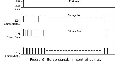
To check the spindle motor control circuit you should trigger 10 ms/div oscilloscope sweep with 2V/div amplification (it is advisable to use 1:10 multiplier). After power-up check for presence of motor start pulses with 11 – 12 V amplitude for three phases (connections J14, J13, J12). The control circuit will try to start the motor for 1 – 2 min., then it will discontinue the attempts. After that you should switch power off/on or send a RESET command by short-circuit of lines 1 and 2 in IDE interface connector using tweezers. If voltage is lower than 10 V for any phase, then U3 chip is malfunctioning. As a result of such failure the spindle motor most likely spins up but remains unable to gain rated rotational speed and, consequently, magnetic heads cannot be shifted from the parking zone. Rotational speed of spindle motor can be controlled using the INDEX pulses at the Е35 control point (if a PCB is connected to the HDA). The frequency of INDEX pulses is ~12 ms, width of INDEX pulses is – 140 nanoseconds. U3 chip is controlled by the U6 synchronization controller chip and the SPINDLE START signal of the spindle motor. For motor start SPINDLE START = 1, for motor stop it is = 0.
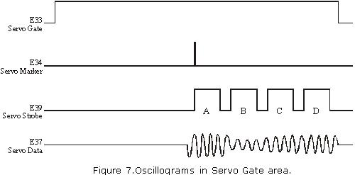
Phase distribution is controlled by the U6 chip through its Fc1 – Fc6 outputs; it uses TTL range of control signals. Feedback of rotational speed is accomplished through the 32Р4910А U11 reading channel chip using the SERVO READ DATA line. In its turn, the U6 synchronization controller chip generates the signal for servo field search (SERVO GATE) for U11 chip.
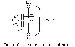
Servo signals and numbers of control points are indicated in the figure 6 and 7. The signals can be viewed more conveniently using oscilloscope with 100 MHz or greater sweep range since INDEX pulses and servo marker last for about ~140 nanoseconds (it is also advisable to use 1:10 multiplier). Monitoring should be performed using two sources, synchronizing the oscilloscope by INDEX or by servo marker. It may be interesting to watch not only servo signals at the Е37 control point but also data reading signals in general at the Е13 and Е7 control points, where one can see all synchronization fields, sectors, etc. (See figure 8).
Details on functioning of control microprocessor, data reading channel and spindle motor control chip are available at web sites of Intel, Silicon Systems Incorporation and SGS-Thomson respectively: www.intel.com and www.st.com.


