Information on data recovery

The three most common problems seen today are: 1. The drive makes a repetitive clicking sound when power is applied (this may not always be audible to you). 2. The drive is completely dead, not spinning at all. 3. The computer bios sees the drive, but there is no boot and a boot from a floppy will not gain access or you get an error message that says ‘Invalid media type reading drive X’. Of course there are other issues such as flooding (never turn a wet drive on!), fire and other natural and unnatural disasters all of which require a top-notch data recovery company to work with.

If your drive is making a clicking sound, 9 times out of ten this means that the heads are bad and cannot read the information needed to get the drive to a ‘ready’ state. This can be due to two factors: physical head crash whereas the heads scrape some of the media off the surface of the platters thus destroying the heads in the process or the heads just go bad. The result is the same, the drive clicks. In this type of situation, you can expect an expensive data recovery because of what is needed to extract the data. The drive will have to be opened in a clean room environment, the heads will need to be replaced which requires an identical drive be purchased just for parts, and a skilled engineer will have to perform the difficult and meticulous task of aligning these new heads so they read the data properly. If indeed the media has been scored, there are many cases where there is nothing that can be done about it because so much of the recording material has been scraped off. Keep in mind that drives now sold are spinning at an incredible 7200 to 10,000 rpm, and that with this kind of speed disaster can be swift when it happens.

There seems to be a large number of electrical issues with drives these days, weather it be natural as in lightning strikes or man-made as in power outages and poorly manufactured power supplies. There are also known issues in many models of Maxtor, Western Digital and Quantum drives where a certain chip will simply burn up and cause the drive to stop spinning. About two years ago or more, Western Digital had a 500,000 drive recall as the result of a defective chip used in making many different models of drives. Over the last year or more, Quantum drives of many models had a similar issue, except this time, the numbers of affected drives was much higher. This was the driving force behind the acquisition of Quantum’s hard drive lines by Maxtor! Maxtor is still reeling from the huge numbers of returned drives on a daily basis. One of the big problems is that manufacturers do not put a fuse on the drives’ electronics anymore. You might say, “This would be an easy fix, I’ll just get another drive of the same model and swap the boards myself”. In an ideal world this would be the case but another factor most people do not know is that for each model drive made by a manufacturer, there can be over a dozen different revisions of the electronics even though the model is identical! This fact can make a simple problem very complex. Don’t look to the manufacturers for help with this either, they will not.

If the drive is seen by the BIOS of the computer, and you cannot access it by booting from a floppy in the case of a WIn9X or ME drive this means that for some reason the areas that define the partitions of the drive or the boot parameters have been corrupted. This can be caused by a virus, a computer or software bug, using a third party partitioning software, running Fdisk or a number of other reasons. This type of situation can be an easy fix for a professional or it can be a more difficult one depending on the extent of any additional damage to the file system or data structures. Usually, this type of problem is an easier one to deal with, because the drive at least still works. In the case of an operating system other than Win9X like NT, corruption the NT data structure can be a very complex mathematical problem and can be an expensive recovery as well due to the time it takes to solve. Operating systems like Unix and Novell as well as Spanned sets or Raid drives can definitely be an expensive recovery due to the complexity of these configurations.

It is important that you never run utilities such as scandisk, Norton disk doctor or any other such utility on a drive you suspect has a hardware failure. This can make recovery of your data difficult or even not impossible in some cases. These software tools work best on simpler types of problems and have no way of dealing with hardware issues. If your data is important, and you have doubts on what to do, call a professional. Also beware of technicians running these tools without your knowledge, as the results can be just as deadly.

When a data recovery company receives your drive, if it is possible and the drive is operational, a copy of your data is made sector by sector onto another drive (make image of your DATA) so that your data is not harmed in any way. This prevents mistakes, and allows the engineer to run utilities and make changes to a copy of your drive only and not the original.

Hard drives these days are worse than ever. You may find this a surprising statement, but it is true. Due to slimmer margins, and high competition, manufacturers are making drives as inexpensively as possible and more failures are the result. As of this moment, Fujitsu has top marks for reliability in desktop hard drives followed by IBM. In notebook drives, IBM and Toshiba have top billing. An important point to note is that Hitachi makes the absolute worst notebook drives in the industry with the highest catastrophic failure rate followed by Fujitsu. Dell has just decided to go exclusively with Hitachi now in their new notebooks, so beware!

Here is my old standby: Make believe that tomorrow when you turn your computer on that it is not going to work, and what is it that you want today that you will have to do without tomorrow! Back it up!
Information on data recovery Read More »

Seagate Malfunctions (Barracuda IV, V and 7200.7)

A very common flaw is disruption of protective diode along the +12V circuit and resulting outage of the computer power supply unit. In that case the external look of that component does not allow identification of the damage, because its case remains unaffected. An attempt to connect a drive so damaged to an operable power supply for diagnostics will most likely result in breakdown of the latter. Therefore if such a drive is brought for repair then first of all you should probe the 0 and +12 V circuit with a regular tester to check for a short circuit.

The protective diode originally designed using the “transil” technology at SGS Thomson is intended for protection of electronic circuitry from short power supply peaks not greater than 10 – 20 microseconds. But in that case their common failures demonstrate that HDD designers did not expect to encounter so poor quality of power supply units. Thus drive operation can be resumed after simple removal of that damaged element from its circuits but we cannot guarantee flawless HDD operation without that component.

Seagate Malfunctions (Barracuda IV, V and 7200.7) Read More »

SSD Flash Hard Drives Data Recovery Video

How Solid State Flash Hard Drives work and how to rebuild them for data recovery. This presentation was at Shmoocon 2008 given by Forensic Expert Scott Moulton from My Hard Drive Died, and Forensic Strategy Services.
Part 1:httpv://www.youtube.com/watch?v=l4hbdZFWGog
Part 2:httpv://www.youtube.com/watch?v=mglEnIPnzjo
Part 3:httpv://www.youtube.com/watch?v=3psy_d-pyNg
Part 4:httpv://www.youtube.com/watch?v=pKeZvhDd5c4
Part 5:httpv://www.youtube.com/watch?v=9XMBdDypSO4
Part 6:httpv://www.youtube.com/watch?v=LY36SWbfQg0

SSD Flash Hard Drives Data Recovery Video Read More »

Advanced Hard Drive Data Recovery Video

New different material! This is a new video on advanced data recovery by Scott A. Moulton. This is from August 2007 at Defcon 15 on how to do your own hard drive recovery.
Part 1: httpv://www.youtube.com/watch?v=vCapEFNZAJ0
Part 2: httpv://www.youtube.com/watch?v=w2FGKD4u8TU
Part 3: httpv://www.youtube.com/watch?v=jAUtv6kOCGE
Part 4: httpv://www.youtube.com/watch?v=5xdboKrOllE
Part 5: httpv://www.youtube.com/watch?v=MydSI4Jv2EI

Advanced Hard Drive Data Recovery Video Read More »

Hard Drive Recovery Video

Hard Drive Recovery presented at Toorcon by Scott Moulton of Forensic Strategy
Services, LLC. Very detailed info on rebuilding hard drives and recovery of your own data.
Part 1:httpv://www.youtube.com/watch?v=Kx-D1nJcv0k
Part 2:httpv://www.youtube.com/watch?v=Tg0Uli2_rwI
Part 3:httpv://www.youtube.com/watch?v=Cayzw1iThjM
Part 4:httpv://www.youtube.com/watch?v=1_sNdPoQdcM
Part 5:httpv://www.youtube.com/watch?v=eOvZZakhihM
Part 6:httpv://www.youtube.com/watch?v=CH6pKDsggZc
part 7:httpv://www.youtube.com/watch?v=TNhajraPuWY

Hard Drive Recovery Video Read More »

IBM malfunctions

Manufacturer: IBM, drive families: DJNA, DPTA, DTLA, AVER, AVVA
Malfunction signs: A drive spins up the spindle motor, recalibrates itself, reports on readiness, BIOS identifies it correctly but at a reading attempt the drive produces “scratching” sounds and reveals numerous BAD sectors on its surfaces.

That malfunction is connected with a mismatch between the cyclical redundancy check code in the data fields and the information recorded in the sector service field. Such a situation appears when recording to a sector is unfinished. That may result from lack of contact at the connector between the PCB and HDA. That connector consists of needle-like pins touching tinned pads on the PCB (please see figure 11). With time soft solder becomes perforated and contact quality deteriorates.

Figure 11. Pin contacts of magnetic heads’ assembly connector in IBM drives (view from behind the PCB)

In order to repair that malfunction you should remove the control board, clean the old solder off the contact pads and cover them again using silver-based solder, then carefully wash the soldered location. Install the board back to HDA. Then you will have to clear the whole disk surface overwriting it with any code using freely available software (please see part 4); that will accomplish recording of correct CRC codes.

IBM malfunctions Read More »

Fujitsu malfunctions

Fujitsu, M1638TAU drive family
Malfunction signs: The spindle motor does not start
The connection scheme of VCM (Voice Coil Motor) & SPM (Spindle Motor) controller is practically identical for the following drive families: M1614TAU, M1638TAU, MPA30xxAT, MPB30xxAT and MPC30xxAT.

VCM&SPM controller regulates 3-phase motor; it is programmed by the MB9004 processor produced by Fujitsu. There are three modes of spindle motor control: start mode, acceleration mode and stable rotation mode. In the start mode at power-up Power Monitor (MP3771) sends a “reset” signal to the microprocessor (MB9004) and the VCM & SPM controller. Microprocessor uses a serial channel to program internal registers of VCM & SPM controller for a start and charges the pump capacitor of the controller using the “Charge pump” signal. Charge volume determines the current which will flow to the spindle motor. As soon as the start-up capacitor is charged sufficiently the microprocessor programs SPM controller for a start mode, then ~ 1,3А current flows to the spindle motor. Controller generates phase switching signals. The spindle motor at that begins rotation generating self-induced EMF. The controller detects EMF and notifies the microprocessor about that; the latter uses the signal for rotation control. In the acceleration mode the microprocessor speeds up phase switching and measures spindle motor rotational speed until it reaches 5400 RPM. When the speed is reached the controller switches to stable rotation. In that mode microprocessor calculates the time required for one spindle motor revolution on the basis of the phase signal and adjusts the rotational speed charging or discharging the pump capacitor. Adjustment control (charge/discharge) is performed every 1/6 spindle revolution.

The complexity of diagnostics is determined by the fact that SPM controller monitors EMF generated during spindle rotation and at an attempt of spindle spin-up it makes just 2 – 3 phase switches which are difficult to track using oscilloscope. If the spindle does not begin rotation (for whatever reason) the controller, as a rule, either switches off or retries its attempt after some time. Thus, if you use a regular oscilloscope, you can see only presence of pulses falling within a certain range, which is insufficient for complete diagnostics. In an ideal case we would recommend using 3-channel oscilloscope with memory function operating in the automatic recorder mode. Probably such device is not really commonplace. Therefore it is possible just to check the presence of pulses for motor phases.

VCM & SPM controller is a quite reliable microchip and it rarely goes out of order. More frequently a spindle motor does not start because of other malfunctions. Still, if the chip fails such failure is usually caused by overheating with clearly visible traces on chip case. During repair of the start circuit you should check the Stop Spindle signal from the MB3771 chip. The signal forces parking of magnetic heads and stops the spindle motor with keys Q8 and Q9. Active level of that signal in the parking mode is “1”, in the operational drive mode it is “0”. If a spindle motor begins to spin up you can check the operation of output keys of HA13525A chip controlling phase signal with oscilloscope. To do so select 10 ms/div sweep with 2V/div amplification (it is advisable to use the 1:10 multiplier). A phase may be diverted by a disrupted Q8 or Q9 key. HA13525A and HA13525B chips are compatible from top downward, i.e. in models belonging to the M1638TAU and MPA drive families both of those chips can be used. In MPB and MPC drive families only HA13525B is allowed.

Manufacturer: Fujitsu, drive families: MPB, MPC
Malfunction signs: A drive begins to detect a higher own capacity than the actual rated value, the so-called “megalomania”.

That malfunction is quite frequent in the above-mentioned drive families; it is caused by corruption of firmware in Flash ROM chip on the control board of the drive. Those drive families employ Flash ROM chips using 64К structure based on 16-bit words, programming voltage is 5 or 12 V, package type is PLCC44.

Elimination of that malfunction requires just reprogramming of Flash chip by recording a known good firmware of the corresponding version. Version number in Fujitsu drives is indicated in the lower right corner of the label over HDA below bar code and it looks like: xyy-zzzz, where x –means the month when the drive was manufactured in hexadecimal notation, yy – means version prefix and zzzz – means the actual firmware version, e.g.: С02-2009. For version compatibility in MPB and MPC drive families just the actual version match is sufficient, the prefix and month of manufacture are not important.

Manufacturer: Fujitsu, MPG3xxxAT/AH drive family
Malfunction signs: Quite unexpectedly for user and user data a drive is no longer identified in PC BIOS.

We should note that this very drive model has broken all records of failures, which happen in most cases after a year of operation, just after completion of the warranty period. The main cause of the malfunction was in the Cirrus Logic CL-SH8671-450E chip. It can hardly be replaced with a working chip because those microcircuits were produced for a special Fujitsu order and the manufacture of that drive family was discontinued long ago. However, there is a method of “revival” and “revitalizing” a malfunctioning chip which allows extending HDD life a little. However, if you ignore drive “hangings” and do not take due steps (at least backup valuable data) the table of S.M.A.R.T. logs in firmware zone will be gradually overfilled and the drive will additionally corrupt its modules in firmware zone, which cannot be restored without specialized software.

One of the versions explaining the cause of problems with those chips is the use of a new polymer compound during production of chip case. The compound decomposes under the influence of increased temperature in humid conditions producing phosphoric acid. But it is just a version; we may never learn whether it is so or not. However, one thing is known for sure: if you unsolder that chip, remove old solder from its pins and contact pads on the board, flush the location for the chip and then solder it back the drive will begin to work properly.

Fujitsu malfunctions Read More »

Quantum malfunctions (Fireball drive families)

Manufacturer: Quantum, Quantum Fireball drive families: EL, EX, CR, CX, lct08, lct10, lct15

Malfunction signs: A drive operates normally for some time (from15 minutes to several hours), then it begins to hit its positioner against the limiting stop.

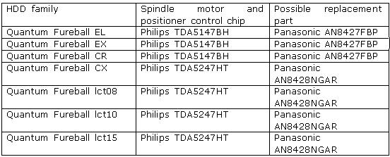
It is a very frequent malfunction in those drive families, it is caused by the chip controlling the spindle motor and positioner; the chip has poor quality of factory soldering (please see the table), overheats because of that and stops to function normally.

One peculiarity of the TDA5247HT (AN8428NGAR) microchip is the availability of space for soldering in the lower part of its case acting, by the way, as its heatsink. It accomplishes heat abstraction from the chip and its dissipation along the board. Thus mounting and removal of that chip should be performed using a thermal air unit.

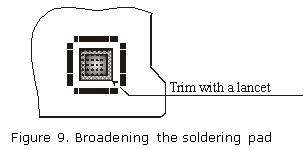
To repair that malfunction, you should unsolder the chip, broaden the soldering pad as shown in the figure 9 (that work can be performed using a lancet for removal of a portion of protective layer), blanch it and the lower part of the chip and solder the latter back pressing its case gently during soldering in such a manner that solder shows through board openings on the other side. Then you should carefully flush the soldered location because that chip has high-resistance analog outputs and fusing agent residue may disturb its normal operation.

That method undoubtedly improves the thermal conditions of the chip but it does not yield positive results always. If a chip used to be overheated for a long time, its resoldering does not remedy the situation. In that case the chip should be replaced. It is advisable to replace it with an identical model offered by Panasonic and having better thermal characteristics. Such chips can be purchased at stores selling electronic components. Its price may vary from 5 to 10$.

Quantum malfunctions (Fireball drive families) Read More »

What Does It Take to Do Forensics?

Hardware
1. Become familiar with the inside of the computer
2. Understand hard drives and their settings
3. Motherboards
4. Power connections
5. Memory

Knowledge of Operating Systems and Software

Operating Systems
–Microsoft Products
–Linux RedHat
–UNIX

Software
–Forensic Software
–HTML
–Microsoft Office
–Quick View Plus

Training
1. New Technologies (NTI) in Gresham, OregonGuidance Software (Encase)Access
DataHTCIA Annual Conference
2. PatienceOne needs the ability to be able to sit in front of the computer
and analyze the data for what could be an extensive amount of time.”No such
thing as point and click forensics.”

What Does It Take to Do Forensics? Read More »

Scroll to Top