Posted in

Locate CHS values for older Seagate, Maxtor, or Quantum ATA drive?

What are the Cylinder, Head and Sector values [C/H/S] for ATA disk drive and how to find them?

C/H/S is an older method of identifying drive capacity and tracking the location of data on the drive. The C/H/S method was replaced with the Logical Block Addressing (LBA) when drives transitioned above 8.4 GBytes. If you are attempting to use a drive smaller than 8.4 GBytes then the C/H/S information can be found by searching the Product Finder in the bottom left corner of the Seagate support site.

For drives larger than 8.4GB it is recommended that the BIOS be allowed to automatically negotiate with the drive using the LBA method.

Note: Changing the C/H/S setting in the BIOS can make existing data on a drive unreadable.

Posted in

Back up folders not listed in ‘Folders Recommended for Backup’ window?

On the Backup and Restore screen in the Mirra application,

  • Click New backup on the Backup Tasks menu.
  • Select a folder to back up from the Browse for folder window and click OK.
  • Click OK in the Confirm Backup Creation window.

You can also select a folder for backup by right-clicking on the folder in Windows Explorer or Control-clicking on the folder in Finder and selecting Add to Mirra Backups on the dropdown menu.

Posted in

APPLE PowerBook doesn’t recognize 1394 storage

Apple PowerBook My Apple PowerBook laptop suddenly stopped responding. The system freezes. When restarted, it does not recognize any FireWire devices.

Download and install the latest firewire drivers from the Apple Software Updates Web site: http://www.apple.com/swupdates. Try these troubleshooting tips as well:

  • If a PowerBook computer with a Maxtor 1394 CardBus adapter will not start up, eject the card. Start the computer again.
  • Do not allow a PowerBook computer to sleep while it is receiving digital video. The video input may not continue when the computer wakes up.
  • If a Maxtor CardBus adapter cannot be removed from the desktop, first power down the computer. Press the card eject button to remove the card.
  • If a PowerBook stops responding to commands, and there are no 1394 devices connected, 1394 system resources may not detect after a restart. If this happens, fully power down the PowerBook and restart.
  • If a PowerBook (FireWire) will not operate in Target Disk Mode, fully shut down the PowerBook and then restart.
Posted in

How to Perform a Software Update on Your Maxtor Fusion

Maxtor Fusion Software Update The following procedure shows you how to perform a software update on your Maxtor Fusion. During the update process, the Maxtor Fusion will be unavailable to active users. Please notify these users before proceeding.

  1. Download the FUSION-x.xx.pkg (where “x” equals the numbers for the update) file to your supported, Windows or Macintosh Client computer.
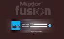
  2. Launch the Fusion’s Web User Interface (Web UI). From the Login Page, login as admin and provide the admin password to authenticate.
  3. From the admin’s home page, click Set Preferences.
  4. From the Admin Applet, click SYSTEM SETTINGS.
  5. The SYSTEM SETTINGS Applet opens. Click the Update button.
  6. You will be prompted to choose an update file. Click the Browse button to locate and select the FUSION-x.xx.pkg (where “x” equals the numbers for the update) file located on your client.
  7. Once selected, click the Update button.
  8. A window opens informing you that the, “Update process has started”. This process will take approximately 5 minutes to complete and during this time, the Fusion will NOT be available to users. Click OK.
  9. At this point the FUSION-x.xx.pkg (where “x” equals the numbers for the update) Update will be loaded to the Maxtor Fusion. When finished, a window opens informing you, “Update complete”. Click OK.
  10. The software update is complete. You can now Logout of the Fusion’s Web UI.

Additional Information:

To confirm that the Update was successful:

  1. Launch the Fusion’s Web User Interface (Web UI). From the Login Page, login as admin and provide the admin password to authenticate.
  2. From the admin’s home page, click Set Preferences.
  3. From the Admin Applet, click ABOUT.
  4. The ABOUT Applet opens. In the upper-left corner of the Applet, you will see (for example if you loaded the FUSION-1.52.pkg):
    Maxtor FusionTM
    Software version FUSION – 1.52

Flash Video that shows you how to perform a Software Update on Your Maxtor Fusion.

Posted in

Global Access File Size Limitations

This article provides comprehensive information about the file size limitation of the Global Access service.

The Global Access service limits file size to approximately 2.0 Gigabytes when uploading or downloading files to your Central Axis over the internet.

This built in file size limitation is in consideration of fairness to the rest of the users in the Global Access community.

The Central Axis server is certainly capable of storing files larger than 2.0 Gigabytes on your local network, but trying to transfer large files over the internet makes for a poor user experience.

Example: You’re at an internet café on a wireless connection thousands of miles away from your home, and the Global Access service. A common connection speed under these circumstances is 56 KiloBytes per second at best. It would take you 3 days, 13 hours, 13 minutes, to transfer a 2.0 GB file, if you were able to stay connected continuously.

Connection speed and download times will constantly vary depending upon distance from the server, current internet traffic, and how many Gateways, ISPs, Routers, and Switches, you have to pass through to connect to your Central Axis drive.

Internet traffic (rush hour) is generally highest in your area right after everybody gets home from work. This is the time of day everybody checks their email. If you are having trouble connecting, staying connected, or transferring files, try waiting a while before contacting your Central Axis through the Global Access service.

There are currently no plans to increase this file size limit.

Posted in

Format a hard drive without using FDisk

Format A Hard Drive STEP ONE
You first need to decide what operating system you intend to load after formatting the hard drive. It is best and easiest to use a boot disk for that Operating System, such as MS Dos6.2 or Windows95b or Windows98SE. You will need the proper Windows95/98 boot disk in order to load the these operating systems on the computer, else it will reject loading due to the wrong Operating System on the computer.

STEP TWO
Insert your boot disk in the floppy drive and start the computer. Once the system has completed booting and an A: prompt appears we are ready to start.

Type: format C: /s [press Enter]

This statement tells the system to format your “C” drive and when it is finished to copy the system files to the drive, (the /s switch for ‘System’). You can format a different drive this way by using a different drive letter.

Format should display: WARNING, ALL DATA ON
NON-REMOVABLE DISK DRIVE C: WILL BE LOST!
Proceed with Format (Y/N)? Type [Y] [Press ENTER]

Your screen should display the size of your drive and a countdown in percentage of formatting completed. Depending on your computer’s speed and the size of the drive it can take from a few minutes to over 15minutes.

STEP THREE
When it reaches 100% complete, you will see a new message:
FORMAT COMPLETE. SYSTEM TRANSFERRED.

This indicates that the files required to boot your computer from the hard drive have been copied from the floppy to the hard drive. The computer can now boot from the hard drive without a boot disk in the floppy drive.

You will see one last message:
Volume label (11 characters, ENTER for none)?
Type anything you like or leave it blank – [Press ENTER]

You can now begin to load your Operating System.
Special Note:
You may receive the error message:
“insufficient memory to load system files”

This is caused by the lack of a memory manager loaded at boot and your PC can only access the first 1mg of ram memory. There are two possible solutions:

1) Omit the /s switch when formatting. This is done by typing this:
FORMAT C: [press enter]

Then when the format is complete, manually add the system files to your hard drive by using this command:
SYS C: [press enter]

2) You will need to load a memory manager in order to overcome this issue. Not knowing what operating system boot disk you are using is an issue here. However, Windows98 boot disks load a memory manager, so let us assume it is either Windows95 or earlier.

You need to add the file HIMEM.SYS to your boot disk and then modify your Config.sys file on the boot disk.

Download Himem Here

and add this line in the Config.sys, (make this the first line):
DEVICE=himem.sys

Now, reboot your computer with the boot disk and it should work fine.

You will find that the boot disks we offer for download are all configured with a Memory manager and contain the file: HIMEM.SYS

Posted in

How to use FDISK to partition a Hard Drive?

FDISK Using FDISK to create a Primary Partition

1. Go to an MS-DOS prompt or use a Boot Floppy.
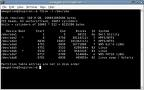
2. Enter -> fdisk
3. Answer the question for large disk support (Y=FAT32 N=FAT)
4. If option 5 exist then you have more than 1 drive attached to your system.
• You need to determine, which drive you are going to partition.
• Enter option 5 and look at your options. It will show you the Drive number and the drive letter associated with it.
• Enter the drive number you wish to select.
• Just a note if you have a Primary Master and a Primary Slave, then the Primary Master will be Drive 1 and the Primary Slave will be Drive 2.
5. Enter Option 4 to “Display Partition Information” to confirm the drive your working with and that there are currently no partitions. If you already have a Primary Master, then you will need to delete it first. (Make sure you save your data first with a proper backup.)
6. Enter option 1 to “Create DOS partition or Logical DOS Drive”.
7. Enter option 1 to “Create Primary DOS Partition”.
8. you will be asked to “Enter Partition size in MBytes or percent of disk space

At this point the drive is ready to be formatted.
If you set this drive up as an additional drive to your existing OS, then you can boot into that OS and begin using the drive.
If this will become a Windows boot disk, you can now start your Windows installation.

Considerations

      •Most functions in

FDISK

      are catastrophic. Make sure to backup your data first.
      •There are two types of Partitions.
      1. Primary.
      2. Extended.
      •

Primary Partition.

      1. Is a boot partition where the Operating System will reside or can also be used for user data.
      2. Each Primary Partition is given a unique Drive Letter assignment. (C:)
      •

Extended Partition.

      1. Each Extended Partition can have one or more Logical Drive(s) within the Extended Partition.
      2. Each Logical Drive is is given a unique Drive Letter assignment. (D:)
      • Hard Drive number.
      1. Windows classifies Hard Drives as Disk Drive 1 through Disk drive n.
      •IDE Drives are scanned in the following order and given a number of 1 through n.
      1. Primary Master.
      2. Primary Slave.
      3. Secondary Master.
      4. Secondary Slave.
      5. Tertiary Master.
      6. Tertiary Slave.
      7. Quantanary Master.
      8. Quantanary Slave.
      • SCSI Drives are scanned from SCSI ID 0 through 16 and given a number of 1 through nn.
      • After entering the FDISK command, you will get a prompt, asking if you want large disk support.
      1. If you reply Y (YES), then you will setup FAT32 partitions.
      2. If you reply N (NO), then you will setup FAT (FAT16) partitions, that have a maximum of 2g.
    3. If you did not receive this prompt then your fdisk command may be from Windows 95 (950A) and you should obtain a newer copy.
Posted in

Can’t partition a SCSI hard drive with FDISK or Disk Utility?

SCSI Hard Drive If you are experiencing difficulty creating a partition on a SCSI disk drive, try these basic troubleshooting steps.

  1. Check all cable connections. Test data cable by trying a different cable or try the cable on a known working drive.
  2. Check the jumper settings.
  3. Check termination.
  4. Check the SCSI controller. Test it by trying a known good controller or a known working drive.
  5. Check SCSI controller default settings. Set the controller to asynchronous negotiation and the transfer rate to 10Mbs (or the slowest setting).
  6. Make this offending drive the only SCSI device in the system and re-test.
  7. Run a SCSI ‘low level’ format routine in the SCSI BIOS Setup Utility.
    Note: This will erase all the data on the drive.
  8. Try the drive in a different system.
Posted in

OneTouch External Hard Drive Operating Temperatures

Hard Drive Temperature The OneTouch Drive feels much warmer than what the spec calls for…should we worry about this?

Problem:
The specifications on the datasheet for my OneTouch drive shows the operating temperature at: 5°C to 35°C (41°F to 95°F)

Cause:
The drive feels warmer than what is stated on the datasheet.

Solution:
The temperature specification identified is not the physical temperature of the drive.  It is the temperature of the room where the drive is. The OneTouch drive will feel much warmer to the touch and can reach temperatures of approximately 55oC and remain within specification.

Posted in

What is ATA/IDE?

ATA IDE Hard DriveWhat is ATA/IDE?
Integrated Drive Electronics
(IDE) is a generic term applied to any drive with an integrated (built-in) disk controller. The first drives with integrated controller were Hardcards. In the IDE architecture, the disk controller is integrated into the drive. This combination drive/controller assembly usually plugs into an interface on the motherboard or an interface card plugged into an empty bus slot. The ATA Specification is simply a set of rules or guidelines that an IDE drive should conform to.

Data transfer modes
PIO-Modes

PIO stands for Programmed Input/Output and was the standard way of using ATA devices but it has become less popular, in favor of the new DMA modes. There are five different PIO modes, each have different transfer rates. The higher the mode number the higher the transfer rate. All PIO modes use the CPU to transfer data which makes this method unsuitable for multitasking environments. Which brings us to the transfer mode used today: DMA.

DMA modes

DMA stands for Direct Memory Access and is the term used when a peripheral device transfers data directly to or from memory, without the use of the CPU. Today DMA is the only feasible way to transfer data from the hard drive to memory as most of todays operating systems use multitasking and can better use the CPU for other tasks. The first DMA modes were not adopted by the popular OS’s of the time, but when Ultra DMA mode entered the scene it quickly became commonplace. The main difference between Ultra DMA and the older singleword and multiword transfers was that Ultra DMA mode clocks the data twice per clock cycle thereby doubling the bandwidth. The most favored today is Ultra DMA mode 2, aka UltraDMA/33.

Standards
ATA-1

To eliminate some major compatibility problems with the early ATA/IDE drives the ATA-1 specification was defined as an ANSI standard in 1994. Previously the most common problem showed up when drives of different manufacturers were placed as master and slave on the same channel.
The original ATA/IDE standard defines the following features and transfer modes:
It supports one or two harddrives on the same bus. One is configured as master and the other as slave.

ATA-2

The ATA-1 standard defined what the interface was capable of a decade ago, and there was a need for faster transfer rates and enhanced features. In 1996 the ATA-2 standard was defined as an ANSI standard that is backward compatible with the older ATA-1.
– Faster PIO modes: 3 and 4.
– Faster DMA modes: 1 and 2
– “Identify Drive” command allows software to query the drive for it’s geometry and characteristics (Plug ‘n’ Play).
Several manufacturers marketed drives based on ATA-2 under different names like “Fast-ATA”, “Fast-ATA-2” and “Enhanced IDE”, which are all marketing terms and not real standards.

ATA-3

In 1997 this ANSI standard was defined and can be viewed as a minor revision to ATA-2 and includes improves the reliability of the faster transfer modes introduced with ATA-2. Also added was the open standard for monitoring disk drive health, SMART

ATA/ATAPI-4

This revision adds some significant and long-awaited features:
– ATAPI (AT Attachment Packet Interface) for devices that require commands not available in the standard ATA standard like CD-ROMs and CD-R.
– Removable Media (Zip drive).
– Overlapped feature set allows devices that require extended time to perform a bus release so that other devices on the bus may be used.
– Ultra DMA data transfer protocol, aka Ultra ATA, which clocks data twice per clock cycle by using both the negative and positive transition.
– Defines an 80 conductor cable to be used for Ultra ATA devices, it is not mandatory however.

ATA/ATAPI-5

Adds Ultra DMA mode 4 or Ultra DMA/66, the 80 conductor cable is now mandatory to maintain signal integrity.

ATA/ATAPI-6

Not finalized yet. It will definately add Ultra DMA mode 5 or Ultra DMA/100 as it is already integrated in drives manufacturered today. Discussions are being held concerning noise reduction which can be found in drives shipping today as well.

Cabling for ATA

It’s easy to describe the different cable types used by the ATA interface today because there really is only one standard. And that is a 40/80 PIN flat cable with 3 IDC connectors. You can attach up to two units on the cable, one master and one slave. The 80 pin cable is for use with Ultra DMA devices but the 40 pin cable can be used with newer Ultra DMA devices but no faster modes than Ultra DMA/33 are available in that case.
In latter years a new cable has emerged, a 44 pin flat cable which is mostly used for 2.5″ internal harddrives. The 4 extra pins are used for supplying power to the drive.

Future for ATA

In order for the ATA interface to cope with the increased data clock rate in the future, a proper terminator has to be applied to prevent “ringing” in the cable. This is not easily solved while achieving backward compatibility and will require cooperation between the major hardware manufacturers to make it work. Perhaps a solution is around the corner as there is a draft for a FireWire ATA interface.