Jumper settings for WD 2.5 inch and 3.5 inch EIDE drives

WD Jumper settings Two different protocols can be used for jumpering EIDE devices, including disk drives. One is the master-slave relationship. With this protocol, one device is jumpered as master and the other is jumpered as slave. The second protocol is cable select. With this protocol, both devices are jumpered as cable select and their position on the cable dictates which device is the master and which device is the slave. The end device is master while the device on the middle of the cable is slave. You can use either of these protocols but you cannot mix them on the same data cable. Both methods refer to having multiple devices attached to the same IDE cable and have options for single drive installations (only 1 drive installed on the system).

1. For Western Digtial 3.5″ EIDE hard drives:

WD Jumper settings

A) Cable Select Configuration Options for PC Systems:

If you have determined that your system and all other IDE devices support Cable Select, please use the following information to connect your IDE drive. The jumper should be on pins 1-2.

Installing the new drive as the only drive in the system:
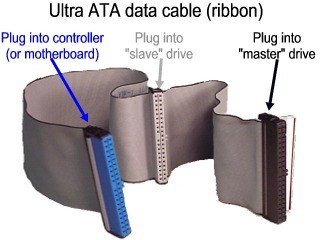
If you are connecting your drive as the only IDE drive on the cable, then there is no need to change the jumper pin on the drive. Simply connect the drive to the black connector at the end of the cable.

Installing the new drive as the primary (Master) drive:
If you are connecting your drive as the primary drive on the cable with another IDE drive, there is no need to change the jumper pin on the drive. Jumper the other IDE drive as Cable Select. Connect the drive to the black connector at the end of the cable for the system and the other IDE drive to the gray connector located at the middle of the cable.

Installing the new drive as the secondary (slave) drive:
If you are connecting your drive as the secondary drive on the cable with another IDE drive, there is no need to change the jumper pin on the drive. Jumper the other IDE drive as Cable Select. Connect the drive to the gray connector in the middle of the cable and other IDE drive to the black connector located at the end of the cable.

B) Master/Slave Configuration Options for PC Systems:

Installing the new drive as the only drive in the system:
If you are connecting your drive as the only IDE device on the cable, then move the jumper shunt on the drive from pins 1 & 2 to pins 4 & 6. Once the jumpers have been configured, connect the drive to the black connector at the end of the cable.

Installing the new drive as the primary (Master) drive:
If you are connecting your drive as the Master drive on the cable with another IDE device, move the jumper shunt on the drive from pins 1 & 2 to pins 5 & 6. Then configure the jumper on the other IDE device as Slave. Connect the drive to the black connector at the end of the cable, and the other IDE device to the gray connector located at the middle of the cable.

Installing the new drive as the secondary (Slave) drive:
If connecting your drive as the secondary drive on the cable with another IDE device, move the jumper shunt on the drive from pins 1 & 2 to pins 3 & 4. Then configure the jumper on the other IDE device as Master. Connect the drive to the gray connector at the middle of the cable, and the other IDE device to the black connector located at the end of the cable.

2. For Western Digital 2.5″ EIDE hard drives:

WD Jumper settings

A) Cable Select Configuration Options for PC Systems:

If you have determined that your system and all other IDE devices support and are using Cable Select, please use the following information to connect your IDE drive. The jumper should always be on pins B-D for Cable Select installations.

Installing the new drive as the only drive in the system:
If you are connecting your drive as the only IDE drive on the cable, please ensure that a jumper is connected to pins B-D on the 2.5″ drive. Simply connect the drive to the end of the cable.

Installing the new drive as the primary (Master) drive:
If you are connecting your drive as the primary (Master) drive on the cable with another IDE drive, please ensure that a jumper is connected to pins B-D on the 2.5″ drive. Please ensure that the second (Slave) IDE drive is jumpered as Cable Select as well. Connect the primary (Master) 2.5″ drive to the end of the cable and the second (Slave) drive to the middle connector of the cable.

Installing the new drive as the secondary (Slave) drive:
If you are connecting your drive as the secondary (Slave) drive on the cable with another IDE drive, please ensure that a jumper is connected to pins B-D on the 2.5″ drive. Connect the 2.5″ drive to the middle of the cable and other (Master) drive to the end of the cable.

B) Master/Slave Configuration Options for PC Systems:

Installing the new drive as the only drive in the system:
If you are connecting your drive as the only IDE device on the cable, no jumper is needed on the 2.5″ drive. Connect the 2.5″ drive to the end of the cable.

Installing the new drive as the primary (Master) drive:
If you are connecting your drive as the Master drive on the cable with another IDE device, no jumper is needed on the 2.5″ drive. Ensure to configure the jumper on the secondary (Slave) IDE device as Slave. Connect the primary (Master) 2.5″ drive to the end of the cable, and the secondary (Slave) device to the middle of the cable.

Installing the new drive as the secondary (Slave) drive:
If connecting your drive as the secondary drive on the cable with another IDE device, please ensure that a jumper is connected to pins A-B on the 2.5″ drive. Configure the jumper on the primary IDE device as Master. Connect the 2.5″ (Slave) drive to the middle of the cable, and the Master IDE device to the end of the cable.

Read More

Jumper Basics

Jumpers are small metallic pins that protrude from the end of a hard disc drive or from its circuit board, as shown below. Jumpers are used to configure the hard disc drive’s options, such as defining master and slave or cable select.

Jumper Jumper

Every pin set has a specific numbering scheme, which is determined by its location on the drive. As shown above left, if the pins are on the circuit board, the pin number assignments are printed on the circuit board around the pins. As shown above right and below, if the jumper pins are on the end of the hard drive, Pin 1 will always be closest to the 4-pin power connector.

Jumper

Below is a jumper shunt, which is used to connect two jumper pins. Connecting two jumper pins with a shunt completes an electrical circuit and enables or disables options of the hard drive. Extra shunts may be stored on a single pin as shown below because two or more pins must be connected by the shunt to complete the circuit and enable or disable options. When the shunt is only on one pin, it is not performing any function.

Jumper

Read More

An Old IDE Drive May Not Work With A New IDE Drive?

Why is it that an Old IDE drive may not work with a New IDE drive?

The reason is the fact that many hard drive manufacturers were already making and selling drives before the IDE standard was clearly defined. Older IDE drives have problems functioning in dual-drive configurations. This scenario is more prevalent when the hard disk drives are from different manufacturers; in some cases, two drives may not function together at all. However, in rare circumstances even new drives will not work together.
Solution:

  • Separate the drives and have them on their own cable. Designate one drive as the Primary Master and the other as the Secondary Master.
  • Try not to jumper the drives as Cable Select. Have the drives jumpered as a “Master” drive.
Read More

Jumper settings for Seagate and Maxtor ATA hard drives

image Master or single drive. If you are installing your Seagate hard drive as the only drive in the system or if it will be the primary boot drive for the system, the jumper should be set as Cable Select. If you are connecting the drive to an older system that has a pre-UDMA Mode 3 ATA controller, or you are connecting this to a cable with a slave device that doesn’t have a cable select jumper setting, jumper the drive as Master instead by putting a jumper on the first vertical set of pins closest to the data cable.

Drive as slave

If you are installing the drive as an additional drive in your system, the drive should be set as Cable Select. If you are connecting the drive to an older system that has a pre-UDMA Mode 3 ATA controller, or you are connecting this to a cable with a master device that doesn’t have a cable select jumper setting, jumper the drive as Slave instead by removing the jumper from the drive.

Cable Select

This setting is the default setting for ATA drives. With the Cable Select jumper set, the BIOS determines whether a drive is a master or a slave by its position on the UltraATA cable. If the drive is jumpered as cable select and is connected to the black connector on the end of the cable, it is recognized as the master drive for that ATA controller. If the drive is jumpered as cable select and is connected to the grey connector on the middle of the cable, it is recognized as the slave drive for that ATA controller.

Drive as master with a non-ATA-compatible slave

On Seagate drives only, set a jumper on pins 5 and 6 and a jumper on pins 7 and 8. Use this jumper setting only if the drive does not work as a master or cable select.

Limit drive capacity (or CLJ)

Use this on computers manufactured before November 1998 when either you start up your computer and see the message, “Hard disc drive controller failure”, your computer does not recognize your newly installed hard drive, or your system stops responding during the boot process after installing this new drive.

Seagate recommends the use of newer UltraATA cables to achieve the best performance from your new Seagate hard drive. These UltraATA cables have 3 colored connectors, each connector has a specific purpose. Be sure to plug the correct connector into the correct device.

Image

  • The blue connector is for your host bus adapter (using a connector on your motherboard).
  • The black connector at the other end is for your master device, usually the hard drive you boot from.
  • The gray connector is for an optional slave device if you have a second hard drive.

Other devices like CD-ROM drives, tape drives and CD burners are usually plugged into a separate cable which also connects to the motherboard.

Seagate U-Series and Barracuda ATA drive families (ie, most ATA drives above 20 GBytes) follow the jumper configuration noted below:

image

Maxtor (and Quantum) drives follow the jumper configuration noted below:

Image

The drive is configured at the factory for a cable select setting. This allows the drive to assume the proper role of master or slave based on the connector used on the cable (see the UltraATA cable figure above). For the cable select setting to work properly, the cables you are using must support the cable select feature. Current UltraATA cables with the 3 colored connectors do support this feature.

Read More

How To Set The Jumper Setting On Samsung (PATA) Hard Disk Drive?

Setting The Jumper On Your Hard Disk Drive

Use the common jumper settings for Samsung hard disk drives that are listed below. Please verify the jumper setting by checking the label on your hard disk drive.

Important: If you partitioned and formatted your hard disk drive, with the General or 32 GB pin setting, and now need to use the opposite pin setting; remember to partition and format the drive again after changing the pin settings.

Configuring your Hard Disk Drive (Master, Slave, or Cable Select) – Setting the Jumper

  • If this is the only HDD in your computer, set the pin setting to Master.
  • If this is the second HDD in your computer, set the pin setting to Slave.
  • If this is the second HDD in your computer, and the first drive is set to Cable Select, set the pin setting to Cable Select.
  • If you are replacing the HDD in your computer, set the jumper setting to match that of the drive you are replacing.

Cable Select:

    • This setting is the default setting for PATA/IDE hard disk drives. With the Cable Select jumper setting, the BIOS determines whether a hard disk drive is Set as Master or Set as Slave by it’s position on the UDMA cable.
    • If the hard disk drive jumper is set to Cable Select and is connected to the black connector on the end of the UDMA cable, it is recognized as Set as Master for that PATA controller.
    • If the hard disk drive jumper is set to Cable Select and is connected to the grey connector on the middle of the UDMA cable, it is recognized as Set as Slave for that PATA controller.Note:When using Cable Select, your system must meet the following conditions:
      • Your systems host controller must support Cable Select.
      • Your hard drives must support Cable Select.
      • Your cable must support Cable Select.

Set as Master:

  • Use this setting if you are installing an additional hard disk drive to a single UDMA cable with a hard disk drive Set as Slave, jumper one hard disk drive to Set as Master, and the other to Set as Slave.
  • Use this setting if you are installing an additional hard disk drive to a single UDMA cable and the Cable Select setting is not recognized.


Set as Slave:

  • Use this setting if you are installing an additional hard disk drive to a single UDMA cable with a hard disk drive Set as Master, jumper one hard disk drive to Set as Master, and the other to Set as Slave.
  • Use this setting if you are installing an additional hard disk drive to a single UDMA cable and the Cable Select setting is not recognized.

32 GB Clip Setting:

Use this on computers manufactured before November 1998 when either you start up your computer and see the message, “Hard disk drive controller failure“, or your system stops responding during the boot process after installing a new drive. This occurs when the hard disk drive is too large for the BIOS to support.

Read More