WD Hard Drive Circuit Boards Swap Guide

As we know:  Western Digital HDD can’t spin; board/chip be burnt; interface broken; etc. These problems are caused by PCB malfunction. Swap PCB of your WD hard drives can resolve the problems. (See also Noise related to PCB in Western Digital hard Drives)

1. WD Hard Drives PCB Swap Guide:

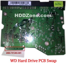
For Western Digital HDDs, just need the donor PCB has the same board number as yours.

western-digital-hard-drive-pcb-swap

2. Before WD PCB Swap you should know:

1. Most PCB’s BIOS chip(ROM Chip) store the unique information. We need change the BIOS form original PCB to replacement PCB, in order to make the replacement PCB compatible with the HDD.  The 8pins (4 pins on each sides) with 25P05VP、25P10VP、25F512、25F1024、25F1024AN、SST25VF512、SST25VF010, etc. are the BIOS Chip.

Tips: Most of the TV/Phone Repair Shop can offer these services for just $5-%20

2. Some PCB don’t have separate BIOS. The BIOS be integrated on the Main Controller IC(The biggest chip on the board, also named Main Chip). We should exchange the Main Controller IC to let the HDD be recognized.

3. Where to buy WD Hard Drive Circuit Boards?

WD 2.5″ Laptop Hard Drives PCB:

WD 2060-771692-002 PCB
WD 2060-771692-005 PCB
WD 2060-771737-000 PCB
WD 2060-771814-001 PCB
WD 2060-771820-000 PCB
WD 2060-771823-000 PCB
WD 2060-771714-002 PCB
WD 2060-771754-000 PCB
WD 2060-701675-004 PCB
WD 2060-701572-002 PCB
WD 2060-771672-004 PCB
WD 2060-771672-001 PCB
WD 2060-701675-001 PCB
WD 2060-701499-005 REV A PCB
WD 2060-701402-002 PCB
WD 2060-701401-002 PCB
WD 2060-701578-001 PCB
WD 2060-701499-000 REV A PCB
WD 2060-701450-011 REV A PCB
WD 2060-701424-007 REV A PCB
WD 2060-701510-000 PCB

WD Hard Drives PCB(SATA)

Western Digital PCB 2060-771702-001
Western Digital PCB 2060-771590-001
Western Digital PCB 2060-701477-001
Western Digital PCB 2060-771640-002
Western Digital PCB 2060-771577-001
Western Digital PCB 2060-771698-002
Western Digital PCB 2060-701640-006
Western Digital PCB 2060-771640-003
Western Digital PCB 2060-701640-005
Western Digital PCB 2060-771668-000
Western Digital PCB 2060-771642-000
Western Digital PCB 2060-701640-007
Western Digital PCB 2060-701567-000
Western Digital PCB 2060-701640-000
Western Digital PCB 2060-701640-001
Western Digital PCB 2060-701640-002
Western Digital PCB 2060-771642-001
Western Digital PCB 2060-701590-001
Western Digital PCB 2060-701563-000
Western Digital PCB 2060-701520-000
Western Digital PCB 2060-701310-004
Western Digital PCB 2060-701537-004
Western Digital PCB 2060-701383-001
Western Digital PCB 2060-701384-002
Western Digital PCB 2060-701453-000
Western Digital PCB 2060-701293-001
Western Digital PCB 2060-701393-002
Western Digital PCB 2060-701444-003
Western Digital PCB 2060-701444-004
Western Digital PCB 2060-701477-002
Western Digital PCB 2060-701537-003
Western Digital PCB 2060-701552-003
Western Digital PCB 2060-701577-001
Western Digital PCB 2060-701590-000
Western Digital PCB 2060-701335-003
Western Digital PCB 2060-701335-005
Western Digital PCB 2060-701310-003
Western Digital PCB 2060-001293-000
Western Digital PCB 2060-001252-000
Western Digital PCB 2060-701537-002
Western Digital PCB 2060-001293-001
Western Digital PCB 2060-701335-002

Western Digital Hard Drives PCB(IDE)

Western Digital PCB 2060-701596-001
Western Digital PCB 2060-001113-001
Western Digital PCB 2060-001092-007
Western Digital PCB 2060-001092-006
Western Digital PCB 2060-001127-003
Western Digital PCB 2060-001076-002
Western Digital PCB 2060-001062-004
Western Digital PCB 2060-001047-001
Western Digital PCB 2060-001100-003
Western Digital PCB 2060-701494-001
Western Digital PCB 2060-701552-002
Western Digital PCB 2060-001068-001
Western Digital PCB 2060-001092-006
Western Digital PCB 2060-001113-001
Western Digital PCB 2060-001129-001
Western Digital PCB 2060-001179-003
Western Digital PCB 2060-701265-001
Western Digital PCB 2060-701292-000
Western Digital PCB 2060-701292-001
Western Digital PCB 2060-701292-002
Western Digital PCB 2060-001130-012
Western Digital PCB 2060-701508-001
Western Digital PCB 2060-701494-002
Western Digital PCB 2060-001130-010
Western Digital PCB 2060-001128-005
Western Digital PCB 2060-001266-001
Western Digital PCB 2060-001266-000
Western Digital PCB 2060-001265-001
Western Digital PCB 2060-001189-003
Western Digital PCB 2060-001177-000
Western Digital PCB 2060-001175-000
Western Digital PCB 2060-001173-004
Western Digital PCB 2060-001159-006
Western Digital PCB 2060-001292-000

Note: These are just PCB (Printed Circuit Boards), not the whole HDD (Hard Disk Drive). More other pcb(Seagate, Maxtor, Samsung, Hitachi) swap guide please refer to this post: hard Drive PCB Swap

Read More

Data Recovery Glossary (Letter P)

PC
Personal computer.

PRML (Partial Response Maximum Likelihood)
A read channel using sampled data, active equalization and Veterbi detection to accurately retrieve the user data off the disk.

Partition
A way to logically divide a hard drive so that an operating system treats each partition as a separate hard drive. Each partition has a unique drive letter.

Passive Termination
A termination architecture that is used to match the impedance at the end of the SCSI bus by using a voltage divider network of passive resistors.

Peripheral
A device that performs a function and is external to the system board. Peripherals include displays, disk drives, and printers.

Platform
A basic design from which a series of products is engineered and produced.

Platter
An actual metal (or other rigid material) disk that is mounted inside a fixed-disk drive. Many drives consist of multiple platters mounted on the spindle to provide more data storage surfaces. Each platter may use one or both surfaces to store data.

Port
A connection or socket on the motherboard or controller card. A motherboard may have one or two ports (primary and secondary). If your motherboard has only one port, you may need to add a controller card to create a secondary port.

Pre-fetch
Instructions that are loaded into a queue when the processor’s external bus is otherwise idle.

Primary Partition
The partition where the operating system files are stored. To start your operating system from a hard disk, it must have a primary partition. You must also make the primary partition active.

Product Road Map
A company’s plan for the introduction of new products.

Protocol
A convention of data transmission that defines timing, control format, and data representation.

Programmed I/O
In a disk drive with an AT interface, data transfers between the drive and host using programmed I/O (PIO). The host uses PIO to write to the Command Block Registers (CBRs) when transmitting control information, such as the location of a read command.

Proximity Recording
A recording technology that increases recording density by allowing the read/write head to come in close proximity to the disk surface.

Read More

Glossary of Samsung Hard Disk Drive (Letter E, F)

Samsung Hard Disk DriveE Block
component that connects the actuator to the head/slider assemblies

ECC
Error Correction Code, detects and correct errors in a data field

Effective Seek Time
The time it takes to seek data, when all/part of the data needed is already stored in the buffer of the drive (speeds up the process)

EIDE (also ATA)
Enhanced Integrated Device Electronics, interface

Embedded Servo
Servo data that is embedded on the media. Allows the actuator to fine-tune the position of the head(s). It is a positioning signal that keeps the read/write heads positioned over the data. The advantage of an embedded servo is that the data can flow without interruptions making the drive suitable for multimedia and AV applications

ESD
Electro-static discharge

FAT
File Allocation Table

FCI
Flux Changes per Inch of data track, equals BPI

Firmware
permanent instructions and data programmed directly into the circuitry of read-only memory (cannot be erased) for controlling the operation of the computer or disk drive

Flux change
reflects the point where the direction of magnetisation reverses in order to define a binary digit (0 or 1)

Format
The arrangement of a magnetic track pattern on the media. This enables the drive to store user data, and is never altered (see also low level formatting)

Form factor
industry standard that defines the dimensions of a particular device (e.g. 5.25″, 3.5″, 2.5″)

Flying Height
the height at which the head moves over the media, a lower height, equals larger areal density

Read More

Hard Disk Details (3)

Slide 1289: The first thing a hard drive will do after it receives power is check for a return status from it’s chips to make sure the electronics are functioning. Then the drive will begin the self-check of its parts and wait for a return status. If both status checks are returned then the drive continues on to the next step and spin up the spindle.

Slide1389: The drive begins to spin the spindle or as you would see, the platters begin to revolve.  When the platters begin to revolve the air flow around the platter creates a force that is called an air bearing.  This air bearing will fling off debris on the platters such as any dust particles or metal fragments from the standard operation of the drive. This air bearing also causes the plastic locking arm mechanism to move out of the way as soon as there is enough air flow for the head to float. Without that airflow the arm is locked in place and will not move over the platter. This is a way to protect the platter from the head touching the platter and causing physical damage. The opposite is true during a power down. When power is cut to the drive, during the last revolutions of the motor, it generates enough power to move the head back to it park position.  Because of this, as you can imagine,  if you get enough power on and power off cycles in a row it is possible for the head to be stuck in the center of the platter and never to be parked correctly causing several types of damage. In certain 80 gig laptop 2.5″ inch drives it is common for the head to be stuck to the center of the platter, never having parked and keeping the platters from spinning. In most cases there is very little damage if the drive is opened and manually turned slow enough not to damage the head, and the data can be recovered, obviously never using this drive again.

Slide 1483: At this point, if the all has proceeded correctly the air bearing will allow the head to float over the platter allowing it to move freely without scratching the surface of the platter.

Slide 1545: At this point, if the head is reading the Servo Timing info from the platter and relaying it to the circuitry so the controller knows the geographic information for the placement of data.  (See previous speech at Defcon 14 for discussion about Voice Coil and stepping motors to understand the servo info).

Slide 1679: At this point the head moves to the System Area (SA) of the platters and reads the content that it requires as well as any additional firmware and overlays.
Most of the time, the system area is on the outer tracks – the extreme outer edge. This is chosen by the manufacturer but is most common on the outside on 3.5 and is sometimes written to the inside tracks on a 2.5″ inch drive.

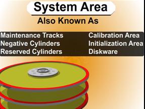
System Area Information Common Names

 1.      System Area
 2.      Maintenance Tracks
 3.      Negative Cylinders
 4.      Reserved Cylinders
 5.      Calibration Area
 6.      Initialization Area
 7.      Diskware

Read More