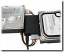
 This is a general description of the most frequently asked questions about the IDE/EIDE Interface. This information is meant only to address basic troubleshooting of IDE/EIDE compatibility issues, and is not meant to be an in-depth discussion of all possible error issues. Our purpose is to aid you in solving basic IDE/EIDE difficulties that may arise.
Issues Covered:
- IDE/EIDE Definitions
- Compatibility Issues
1. What is IDE/ATA?
Integrated Drive Electronics (IDE) is a generic term applied to any drive with an integrated (built-in) disk controller. The first drives with integrated controller were Hardcards. In the IDE architecture, the disk controller is integrated into the drive. This combination drive/controller assembly usually plugs into an interface on the motherboard or an interface card plugged into an empty bus slot. The ATA Specification is simply a set of rules or guidelines that an IDE drive should conform to.
2. What does the IDE interface actually do?
The primary job of the IDE interface is to transmit/receive data to and from the drive.
3. Why place the Controller on the drive itself?
Placing the controller on the drive gives IDE drives built-in reliability because data encoding, from digital to analog is performed directly on the drive in a tight, noise-free environment. The timing-sensitive analog information does not have to travel along ribbon cables that may pick up noise and insert propagation delays into the signals. The integrated configuration allows for increases in the clock rate of the encoder, as well as the storage density of drive.
4. What is Enhanced-IDE (EIDE) and Fast-ATA?
Enhanced IDE (EIDE) was a marketing program first initiated by Western Digital. EIDE has two sides:
- Software – the Enhanced BIOS Specification that surpasses the 504 MB hard drive capacity limitation
- Hardware – hard drives that conform to the ATA-2 and ATA-PI Standards
Fast-ATA, EIDE’s counterpart, was a separate marketing program that was introduced by Seagate and Quantum. This program leaned conservatively toward the ATA-2 specification.
5. What are the main features of EIDE
These are the main features:
- Faster transfer modes- PIO modes 3-4, DMA mode 2 and UDMA.
- Multiple Read/Write commands
- LBA mode, translation for drives larger than 504 MB
- Four devices on the ATA controller (secondary port)
- CD ROM and Tape Drive support
6. Is ATA-5, 6 or 7 compatible with older IDE drives?
Older IDE peripherals will work with newer enhanced drives. However you will not be able to fully utilize the enhanced features of your ATA-5, 6 or 7 peripherals.
7. Is ATA-5, 6 or 7 compatible with older IDE controller cards?
EIDE drives are backward compatible with non-EIDE (standard) controller cards. However, an EIDE card will only perform at the capabilities of the controller; hence the EIDE drive will perform like a standard IDE drive.
8. What is ATA-PI
AT Attachment Packet Interface (ATA-PI) is a standard that implements SCSI like devices on the ATA bus. Devices like CD-ROM’s, tape drives and other removable media. The advantages of ATAPI are:
- It is inexpensive
- It is easy to implement in current systems.
ATAPI’s disadvantage is that it requires the use of software drivers for operability.
9. What is Cable Select (CSEL)?
Cable Select (CSEL) is an optional feature per the ANSI ATA specification. It is an alternative method of identifying the difference between device 0 and device 1 on an IDE interface cable. Hard drives configured in a multiple drive system are identified by CSEL’s value:
- If CSEL is grounded, then the drive address is 0.
- If CSEL is open, then the drive address is 1.
Additionally, CSEL requires a specialized (and more expensive) 40-pin 80-wire IDE interface cable, unlike the standard EIDE interface cable that is far more commonly used. We do not recommend using the CABLE SELECT feature unless your specific computer system documentation requires its use.
10. How does my computer know which drive is the Master and which is the Slave?
When only one drive is installed, the single drives controller responds to all commands from the system. When two drives (which means two drive controllers) are installed, both controllers receive all commands from the system. Each drives controller must then be configured to respond only to commands issued to it. In this situation, one controller must be designated as master and the other as slave. When the system sends a command to a specific drive, the other drive’s controller must remain silent. A special bit (the DRV bit) is used in the Drive/Head Register to distinguish between the controllers.

