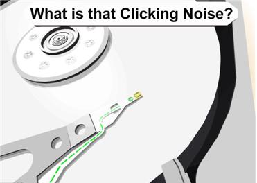
Hard Disk Details(6)

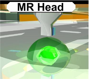
Slide 2840: The GMR (giant magnetoresistive) head is the current head used on most hard drives. This head uses high end physics I do not claim to understand. The only major difference is the way the head has been changed to read perpendicular. The GMR head has four layers, a sensing layer, a conducting layer, a pinned layer and an exchange layer.  It was discovered that if you took two magnetic layers and aligned them opposite each other with a soft layer between them that the magnetic force would align themselves in parallel. When a bit of data passes under the heads the electrons bounce around in the layers causing the pinned layer to spin.
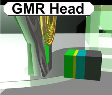
For more info, read http://www.hitachigst.com/hdd/technolo/gmr/gmr.htm
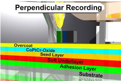
Slide 2865: Hard drives have switched to Perpendicular Recording.  I talked about the changes and previous versions last year and you can reference that speech for more info. The biggest change switching to perpendicular is that the data is written up and down instead of longitudinal. Because of this, changes had to be made to the platter so it would not interfere with reading and writing.
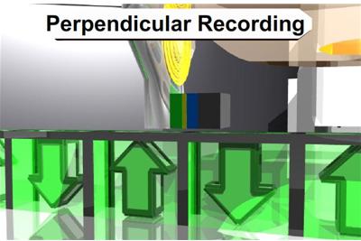
Slide 2885: The coatings have changed and  the substrate on the bottom (the platter itself) was the biggest change. Almost every platter has converted to a glass ceramic platter.  What this means to you in data recovery is that it is obvious when a scratch occurs. In most cases you will be able to see though the platter. Sometimes the rings that are created by the scratch are so smooth that they look like they are supposed to be there.  I assure you that they are not.  It should be silver from one edge to the other with no rings at all.  So if you see a ring, in most cases the game is over or your recovery just got a lot harder.
Slide 3000:  The data structure that is written to the sectors is important to understand if you are using any diagnostic software.  Many of them use common nomenclature to discuss the types of errors.

Common Error Codes and Diagnostic Info from Most High End Software:
BSY – drive busy
DRDY – Drive ready to accept commands
ERR – The Last Result was an Error
DREQ -exchange data with host
UNCR-Uncorrectable Error
WRFT – Write Fault
AMNF-Address Marker Not Found
IDNF- Sector ID Not Found
ABRT- Command Aborted
TONF – Track 0 not found

You will see the error codes here in almost all data recovery and diagnostic software.  This particular block of data (slide 3259) is one single sector. It contains a 512 byte block of data.  This is how on sector looks to every hard drive regardless of your operating system.

I could not possibly explain every error you will see, but I can give you the basics of the most common you will see doing diagnostics.

 IDNF is the Address not found. If the sector that holds this information is corrupt there is no way for the hard drive to locate this sector and it will return the result IDNF.

 AMNF is the Address Marker Not Found. This is similar to the IDNF but relates to the data. If there is an error and this marker is corrupt then the data for this sector cannot be located. The data in this area is 512 bytes of user data.

 ECC is that there is a problem reading from ECC and it does not match. ECC is used to check the integrity of the data being read. When the data is read the drive calculates the ECC and compares. If there is an error the drive will retry until it cannot get a correct result and then will return the UNC error.

 UNC will happen when the data is uncorrectable data error.

 ABRT is an abort error and it will discontinue trying to read that block
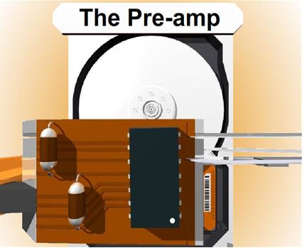
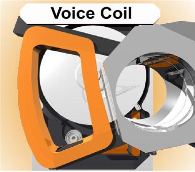
Slide 3559: The preamp is a chip that amplifies the signal coming from the heads of the drive. Since the data that is read coming from the heads is similar to a wave form from a speaker, the preamp will amplify it and send it on to the electronics for decoding. There are two types of preamps, one is soldered on, and the second is glued on.  It is often possible for a preamp to come loose due to heat expansion and not to have a good connection to the board. It is also possible for the preamp to fail. This is one of the causes of the click of death for the hard drive. It is often difficult to replace or fix this circuit and is more likely you can do a platter swap to a good drive, or replace the head stack assembly. The voice coil was mentioned in previous information at Defcon 14.
Click of Death and Hard Drives Safe Mode Notes
Errors cause the drive to constantly shutdown and recalibrate, this is a sound or movement that can usually be heard or seen and is known as the Click of Death for hard drives. If drive parts are good then rewriting the SA area is the part that needs repairing. The difficultly is in knowing if the rest of the parts are good. The SA can only be rewritten by a few devices. There are a few ways to get around this; one of the ways is a live PCB swap. Again the SA is not accessible over the interface without special tools.

Most hard drives have a specific recalibration routine they use to retry the SA area. Even though it cannot be read most drives will continue this routine.  A few drives will, after a certain number of times automatically power down.  The normal timing routine for this process is:
         Two head clicks
         power down
         two head clicks again
** Some drives will perform three head clicks before powering down.

Maxtor drives will test all heads from 0 to F; it must come out to level F, or stop the spindle. The problem of Quantum drives of all series (including last series — known as Maxtor D540X and D740X) can be detected by the specific sounds: after starting, there will be two loud clicks, then drive’s motor will increase its speed, and there will be 4 more clicks, after which the drive will become “ready”. For Western Digital a dead preamplifier is also detected by the specific sounds: after two loud clicks the drive will stop the spindle. If you have a clicking Maxtor then heads malfunctioning is characterized with a continuous clicking for over 30 seconds. Samsung drives with a dead preamplifier also click two times and then stop the spindle; however, for Samsung drives it can also mean problems with reading of the critical modules of the system area.

Hard Drives Safe Mode
Can be done by setting jumpers in case a module is damaged or some drives can detect it and go into safe mode itself. In safe mode the drive bypasses its own firmware and is waiting for firmware to be uploaded to ram. The RAM code is called the loader and will start the drive operations. It is possible for the hard drive to go into safe mode all by itself if it detects a problem. You will never know this is happening on purpose. Some software like MHDD might be able to tell you if your drive is in safe mode. You will never be able to recover data until this problem is solved and it is not running in safe mode. When it is running in safe mode it will sound like the Click of Death on most hard drives.

Diagnostic software called MHDD or Victoria
http://hddguru.com/content/en/software/2005.10.02-MHDD/

MHDD Software commands and functions:
Erase Waits:- It is better to use this for Drive Repair but it is data destructive
HPA :- Host Protected Area Functions
REMAP: – Try to recover bad sectors
Standby: – turn the motor off
PWD: – User Password INFO
Dispwd: – disable the password
Fdisk: can make one full size fat 32 drive
Hard Disk Details(6) Read More »

Hard Disk Details(5)

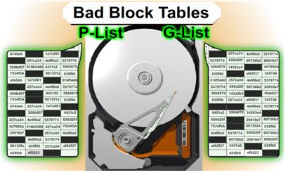
Slide 2221: When the drive is manufactured it is known that there is going to be errors in every drive.  Drives use ECC to correct most errors and if ECC can correct the error then the sector is never marked as bad.  If it is marked as bad, the drive puts the data in a bad block list. Most people know that their hard drive has a bad block table. What most people do not know is that their drive has TWO bad block tables.
1.    P-List (Primary Defects List – manufacture defect info that does not change)
2.    G-List (Grown Defects Lists – sector relocation table)

The G-List is where the bad blocks that your drive has on a daily basis are stored. Since the P-List is done at manufacturing time that list is never suppose to change. There is a very important reason to know about both lists in a low level recovery which I will explain when we get to the repair section. There are certain utilities that can read, delete, merge and change this data.

ECC Notes and Issues

ECC structured redundancy up to 200 bits of 256/512 in a sector-CRC–Scrambled Bits- RLL adds bits to cause pulses and Parity When data is written to the drive it is encoded. The actual data itself is never written, only the interpretation of the data. If you are thinking that a drive contains 0’s and 1’s then you are thinking about it incorrectly. The data is more like a wave form being written to the drive. It has to be interpreted back on its way out before it becomes a 0 or a 1. Before the data is written the data is randomized. This eliminates patterns that might be the same so that ECC is not confused. It is difficult to do pattern detection on a pattern that appears over and over. EMI can be reduced and have less effect on the bit storage and the timing controls.

The drive tries several different ways to re-read the data before giving up, most of them using ECC. It is possible for ECC to improperly correct data under certain circumstances if the data occurs in a certain order. ECC read commands use ODD numbering of at least 3 so as not to cause a 50/50 chance in the selection of 2.

Read ignoring ECC is an LBA 28 command “Read Long” and it was disabled in 48 bits as it was determined to be obsolete in drives over 137 gigs. No Read Ignore ECC is available after 137 gigs. Standard attempts are tried and usually are 10 tries in most hard drives. Reading a drive ignoring ECC can cause possible corruption in the data, but sometimes it is the only way to get the data in those sectors if there is a problem with the PCB or the ECC cannot read the data correctly.

If the Sector is determined to be unreadable by the ECC encoder then the sector is retried again. Reed Solomon in conjunction with sector rereads is expecting to fix data errors for the ECC. Parity bits are stripped off.

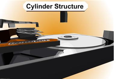
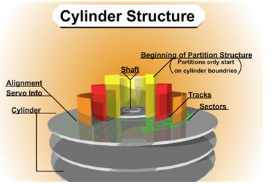
Slide 2422: The cylinder structure is extremely important because there are people believe they can just take the platters out and move them to a new drive. This is true you can do this, but you have to move all platters simultaneously. The reason is because data is written in a cylinder.  Most people have heard the term cylinder in reference to their hard drive, but they have no idea what that means. Writing in a cylinder means that data is written in parallel due to the fact the heads are always moving together in the same stack.  To make it more efficient data is written on the top of a platter and the bottom of the platter and the next platters and so on, at the same time.  Your data is NOT written on the top of one platter and when that gets full then written to the next platter. It is written across all the platters at the same time, making a cylinder of your data.

Most data recovery software will scan an entire hard drive and then display a list of files and directory trees you can recover from. However, if there is a lot of damage to the drive, the scanning may never finish or it might die/kill it in the process. If you have smart software and you can figure out where your partitions start and where the MFT or FAT tables might be, you stand a better chance of getting the data you are looking for.  If a standard utility was used to create the partition then the partition structure will begin on a cylinder boundary. Again, your partition will begin on a Cylinder Boundary. Software like Byteback (www.byteback.org) RecoverSoft Media Tools Pro (www.recoversoft.com), and Runtimes Disk Explorer (www.runtime.org) are smart enough to know the data exists on the cylinder boundary and will quickly check without you have to scan the whole hard drive and possibly saving your drive from disaster during the scan. There certainly are times that scanning will be required but it is best if you can avoid it except in an imaging process.

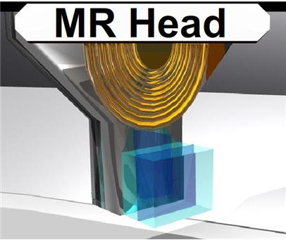
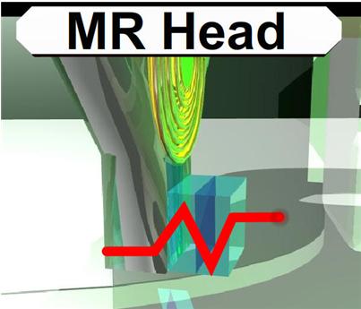
Slide 2585: The MR (magnetoresistive) head of the hard drive you can think of as the head of the 90’s. If you remember how reliable the drives were before 2000 it is mostly because of this head and the density of the platters.  This head was used on drives mostly before we crossed the 10-20 gig barriers. The MR head could determine if a bit passed under it.  When data passed parallel to the head, the head could detect the “MR Effect” due to movement of electrons causing the magnetic field to rotate positive and negative values.

Hard Disk Details(5) Read More »

What the role of the computer in the forensics is?

A computer can be the target of the crime, it can be the instrument of the crime, or it can serve as an evidence repository storing valuable information about the crime. In some cases, the computer can have multiple roles. It can be the “smoking gun” serving as the instrument of the crime. It can also serve as a file cabinet storing critical evidence. So when investigating a case, it is important to know what roles the computer played in the crime and then tailor the investigative process to that particular role.

In most cases, the computer forensics specialist will take several careful steps to identify and attempt to retrieve possible evidence that may exist on a subject computer system:

1. Protect the subject computer system during the forensic examination from any possible alteration, damage, data corruption, or virus introduction.

2. Discover all files on the subject system.This includes existing normal files, deleted yet remaining files, hidden files, password-protected files, and encrypted files.
3. Recover all (or as much as possible) of discovered deleted files.
4. Reveal (to the extent possible) the contentsof hidden files as well as temporary or swap files used by both the application programs and the operating system.
5. Accesses (if possible and if legally appropriate) the contents of protected or encrypted files.
6. Analyze all possibly relevant data found in special (and typically inaccessible) areas of a disk. This includes but is not limited to what is called unallocated space on a disk (currently unused, but possibly the repository of previous data that is relevant evidence), as well as slack space in a file (the remnant area at the end of a file, in the last assigned disk cluster, that is unused by current file data but once again may be a possible site for previously created and relevant evidence).

7. Print out an overall analysis of the subject computer system, as well as a listing of all possibly relevant files and discovered file data. Further, provide an opinion of the system layout; the file structures discovered; any discovered data and authorship information; any attempts to hide, delete, protect, or encrypt information; and anything else that has been discovered and appears to be relevant to the overall computer system examination.

8. Provide expert consultation and/or testimony as required.

What the role of the computer in the forensics is? Read More »

Hard Disk Details(4)

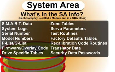
Slide 1781: What is in the System Area Info. Each category is called a Module and is a UBA block.

1.    Smart Data
2.    System Logs
3.    Serial Number
4.    Model Numbers
5.    P-List (Primary Defects List – i.e.: manufacture defect info that does not change)
6.    G-List (Grown Defects Lists – sector relocation table)
7.    Program Overlays – Firmware, Executable Code, or updates
8.    Specific Tables like RRO – (recalibrate repeatable run-out and head offsets)
9.    Zone Tables
10. Servo Parameters
11. Test Routines
12. Factory Defaults Tables
13. Recalibration Code Routines
14. Translator Data
a.    Converts Logical and Physical Address to locations on the drive
b.    Heads and Track Skewing Info
15. Security Data Passwords for drive – possible encrypted info.

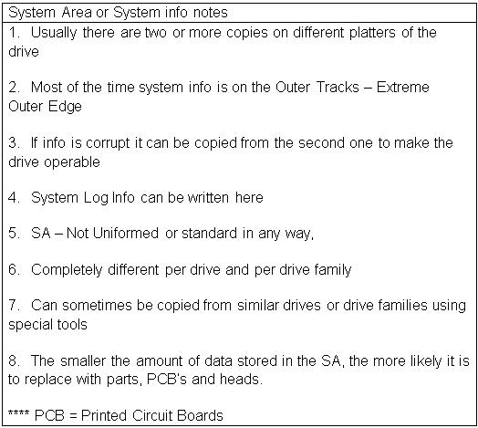
System Area or System info notes
1.    Usually there are two or more copies on different platters of the drive
2.    Most of the time system info is on the Outer Tracks – Extreme Outer Edge
3.    If info is corrupt it can be copied from the second one to make the drive operable
4.    System Log Info can be written here
5.    SA – Not Uniformed or standard in any way,
6.    Completely different per drive and per drive family
7.    Can sometimes be copied from similar drives or drive families using special tools
8.    The smaller the amount of data stored in the SA, the more likely it is to replace with parts, PCB’s and heads.
**** PCB = Printed Circuit Boards

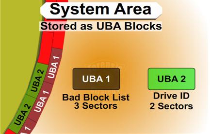
Slide 1816: The System Area is made of UBA Modules (Utility Block Addressing) which are sector blocks logically grouped together that contain a specific MODULE.  Each UBA block might be different per a drive manufacturer. The UBA # might be Smart Data on one drive and a different type of data on another drive. The UBA area is inaccessible over the standard interface. Most of the commands to talk to the UBA modules are vendor specific and which is generally not made publically available. There are certain pieces of hardware that can be used to communicate with this area such as the PC3000.

For example: In the UBA 1 Area it could be a Bad Block List.  As larger drives have been created there has been a need for larger bad block areas.  So this might be expanded from two sectors in a previous drive to three sectors in a newer drive. But the firmware for the drive can still refer to each of them as UBA 1 and does not have to have any changes made to the code in the firmware regardless of the size change.

Hard Disk Details(4) Read More »

Hard Disk Details (3)

Slide 1289: The first thing a hard drive will do after it receives power is check for a return status from it’s chips to make sure the electronics are functioning. Then the drive will begin the self-check of its parts and wait for a return status. If both status checks are returned then the drive continues on to the next step and spin up the spindle.

Slide1389: The drive begins to spin the spindle or as you would see, the platters begin to revolve.  When the platters begin to revolve the air flow around the platter creates a force that is called an air bearing.  This air bearing will fling off debris on the platters such as any dust particles or metal fragments from the standard operation of the drive. This air bearing also causes the plastic locking arm mechanism to move out of the way as soon as there is enough air flow for the head to float. Without that airflow the arm is locked in place and will not move over the platter. This is a way to protect the platter from the head touching the platter and causing physical damage. The opposite is true during a power down. When power is cut to the drive, during the last revolutions of the motor, it generates enough power to move the head back to it park position.  Because of this, as you can imagine,  if you get enough power on and power off cycles in a row it is possible for the head to be stuck in the center of the platter and never to be parked correctly causing several types of damage. In certain 80 gig laptop 2.5″ inch drives it is common for the head to be stuck to the center of the platter, never having parked and keeping the platters from spinning. In most cases there is very little damage if the drive is opened and manually turned slow enough not to damage the head, and the data can be recovered, obviously never using this drive again.

Slide 1483: At this point, if the all has proceeded correctly the air bearing will allow the head to float over the platter allowing it to move freely without scratching the surface of the platter.

Slide 1545: At this point, if the head is reading the Servo Timing info from the platter and relaying it to the circuitry so the controller knows the geographic information for the placement of data.  (See previous speech at Defcon 14 for discussion about Voice Coil and stepping motors to understand the servo info).

Slide 1679: At this point the head moves to the System Area (SA) of the platters and reads the content that it requires as well as any additional firmware and overlays.
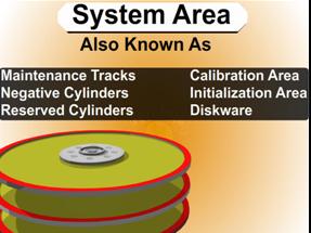
Most of the time, the system area is on the outer tracks – the extreme outer edge. This is chosen by the manufacturer but is most common on the outside on 3.5 and is sometimes written to the inside tracks on a 2.5″ inch drive.

System Area Information Common Names

 1.      System Area
 2.      Maintenance Tracks
 3.      Negative Cylinders
 4.      Reserved Cylinders
 5.      Calibration Area
 6.      Initialization Area
 7.      Diskware

Hard Disk Details (3) Read More »

Hard Disk Details (2)

The hard drive knows nothing about your files and is not aware in any way of the content. That is the job of the Operating System (OS from here on). When the OS asks for a file, the OS will request a logical block from the drive; the drive will translate that to the physical location in CHS. An example is that it might request data from Cylinder 2500 at head 2 located on sector 234. The drive has many spare sectors and sometimes spare tracks to be used to compensate for errors and relocation of data. NOTE: Look at $BadClus on a NTFS File system for what the OS thinks is bad.

In a previous speech here at Defcon 14, I gave the basic inner workings of a hard drive and several ways you can repair it. I am sure that you can get that previous speech on DVD, find it on the web, or on www.myharddrivedied.com and it will give you a large amount of info that I am not going to discuss here today.  Additionally, there is a whitepaper on the CD that includes more data and notes about repairing a hard drive.

Since my last speech one of the most common questions I get everyday is “What is that clicking noise? How do I fix it?” This is not a simple problem by any means.  So my goal today is to give you more insight into the inner workings your hard drive and explain how this problem occurs and what you might be able to do to fix it.

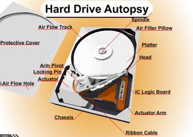
Slide 1208: In this speech we are looking at the platter assembly where the heads are located, through the area of the preamp and the IC Logic Board down to the PCB.  This is the area that affects what is causing the clicking noise that you hear.  I am now going to explain how each of these things works and walk you through the drive functions.

Part of what causes this clicking problem is related to the power on routine functions.

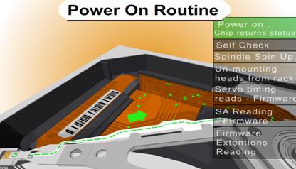
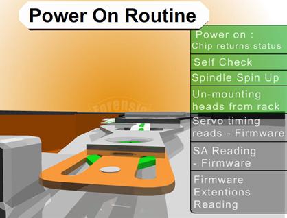
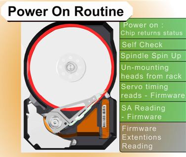
The boot sequence of a drive is as follows:
1.      Power on chip returns status
2.      Self check
3.      Spindle spin up
4.      Un-mounting heads from rack
5.      Servo timing reads – firmware
6.      SA reading – firmware
7.      Firmware extensions reading
8.      Error – read SA from other secondary copies

Hard Disk Details (2) Read More »

Hard Disk Details (1)

Data recovery is necessary when source material fails and where no good backup exists, either Physical or Logical. There are two types of data recovery in the standard basic sense.  One type of data recovery is when there is damage to the media and the pre-existing data need to be retrieved. This will usually require the media to be repaired.

The second form of data recovery is when files were purposely or accidently deleted.  When this type of data recovery is necessary there is usually no damage to the media and standard software can be used to recover the data.  This is the process that most software performs. Very few software programs understand damaged media. Because most software relies on calls and functions from the operating system for its input, it has no control itself over error correction or any functions that the operating system performs on the drive. I believe there a four phases to any data recovery.

Four Phases of Recovery
1. Repair the Hard Drive so it is running in some form, usually requiring hardware or special equipment.

2. Image, Copy or recover the physical drive and sectors primarily by bitstream imaging. If the drive is functioning, it is possible to do this with software, however there are some hardware solutions that work very well; i.e. DeepSpar Disk Imager. This is a situation where some software is better than others, such as dd_rescue (use with dd_rhelp script) on a Linux system has a special feature that allow it to image backward (understanding why you need to image backwards is very important in data recovery).

3. Perform Logical Recovery of files, partition structures, or necessary items; usually this is by software and is the most common type of application sold.

4. Repair of files that might have existed in damaged space or sectors to recover what is possible.  This is usually the requirement in Forensics to be able to re-assemble data to display what was there, if whole or not. This is also applied in data recovery for corrupt Word and Excel documents.

Hard Disk Details (1) Read More »

Computer Forensic Tool: MacLockpick

MacLockpickMacLockPick™ is a valuable tool for law enforcement professionals to perform live forensics on Mac OS X systems. The solution is based on a USB Flash drive that can be inserted into a suspect’s Mac OS X computer that is running (or sleeping). Once the software is run it will extract data from the Apple Keychain and system settings in order to provide the examiner fast access to the suspect’s critical information with as little interaction or trace as possible. And also this is the only professional tool which can be use to extract the extensive encrypt information under the close-down condition of computer.

Computer Forensic Tool: MacLockpick Read More »

Computer Forensic Tool: F-Response

F-Response: The First Truly Vendor Agnostic Solution for Remote Forensics and eDiscovery

In the alibi or the enterprise inner investigation, how to completely do the physical data extraction from a running computer? How to do computer forensic on the running Mac OS, Linux, Window, the three different computer operation system? How to do computer forensic to the running server? How to do research on any computer in the local area network? With the F-Response software, all of these are possible. F-Response uses a patent-pending process based on well documented industry standards to create a secure, read-only connection between the examiner’s computer and the computer under inspection.

F-Response can be used with any kind of computer forensic tools. You may know that any error operation may change the source data, but F-Response connection is completely read-only, functioning much like a software write blocker, to make sure the data safe.

F-Response is available under the following three different licensing options which are designed to appeal to independent examiners, consultancies, and corporations:

The F-Response Field Kit Edition is a value priced single user version of the F-Response patent-pending software suite. An F-Response Field Kit, when physically connected to the remote computer, will give you access to all the physical drives on that remote computer via the network. Best of all the Field Kit is licensed for one year and priced at less than one typical hour of consulting time!

The Consultant Edition of F-Response was built and designed around the needs of larger and geographically distant consulting teams. Using F-Response Consultant Edition you will be able to simultaneously access multiple computer physical storage devices with a single Consultant Edition software key. F-Response Consultant Edition is an excellent choice for First Responders and Incident Response teams

The Enterprise Edition of F-Response is the service based (Non GUI) version, which is uniquely designed for Managed Services consulting and internal corporate wide deployments. F-Response Enterprise Edition provides all the features of F-Response Consultant Edition, streamlined for large network deployment, with a scriptable installation and is designed to support either an internal corporate investigations team or a managed services appliance. Best of all, F-Response Enterprise is not licensed on a seat basis.  One license of F-Response Enterprise provides unlimited usage on an unlimited number of client installations for a full year.

Computer Forensic Tool: F-Response Read More »

Computer Forensic Tool: X-way Forensics

X-Way Forensics: Integrated Computer Forensics Software

X-Way Forensics is an advanced work environment for computer forensic examiners. It provides a strong, compositive environment of forensic and analysis. It comprises all the general and specialist features known from WinHex, also it has more powerful functions:

It provides a function formidable, the synthesis evidence collection, the analysis environment, is also called the WinHex law card version

Disk cloning and imaging, even under DOS with X-Ways Replica (forensically sound)
Examining the complete directory structure inside raw (.dd) image files, even spanned over several segments
Native support for FAT, NTFS, Ext2/3/4, CDFS, UDF
Built-in interpretation of RAID 0 and RAID 5 systems and dynamic disks
Complete access to disks, RAIDs, and images more than 2 TB in size (more than 232 sectors)
Viewing and dumping physical RAM and the virtual memory of running processes
Various data recovery techniques and file carving
File header signature database, based on flexible GREP notation
Hard disk cleansing to produce forensically sterile media
Gathering slack space, free space, inter-partition space, and generic text from drives and images
File and directory catalog creation for all computer media
Easy detection of and access to NTFS alternate data streams (ADS), even where other programs fail
Mass hash calculation for files (CRC32, MD5, SHA-1, SHA-256, …)
Unlike a competing product, does not depend exclusively on MD5 (collisions in MD5)
Powerful physical and logical search capabilities for many search terms at the same time
Recursive view of all existing and deleted files in all subdirectories
Automatic coloring for the structure of FILE records in NTFS
Bookmarks/annotations
Bates-numbering files

Computer Forensic Tool: X-way Forensics Read More »

Scroll to Top